16
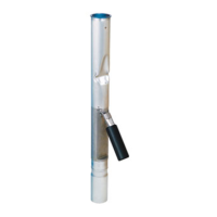
STEP 25: INSTALL WARNING PLATE
Bend the three warning plate ears down then slide the
tie wrap over the warning plate ears and position warn-
ing plate against riser pipe approximately 1" below the
adaptor. Tighten the tie wrap securely. The valve is
now fully installed and in operating position.
NOTE: the warning plate includes important warn-
ings, operating parameters, and listing information
and must be installed.
STEP 26: VALVE REMOVAL
The valve can be removed for tank leak testing, inspec-
tion, etc., by removing the Rotatable Product Adaptor,
the 4" nipple, and the Jack Screw Kit. Reinstall per the
above instructions.
For testable models only: It is not necessary to re-
move the valve to check poppet movement / function.
See Page 17 for full testing details.
STEP 27: ELECTRONIC LIQUID LEVEL MONITORING
If an electronic level monitor is installed, it must be cali-
brated to match the top of the 71SO valve body, which
must correlate with 95% of the actual tank capacity.
Figure 25
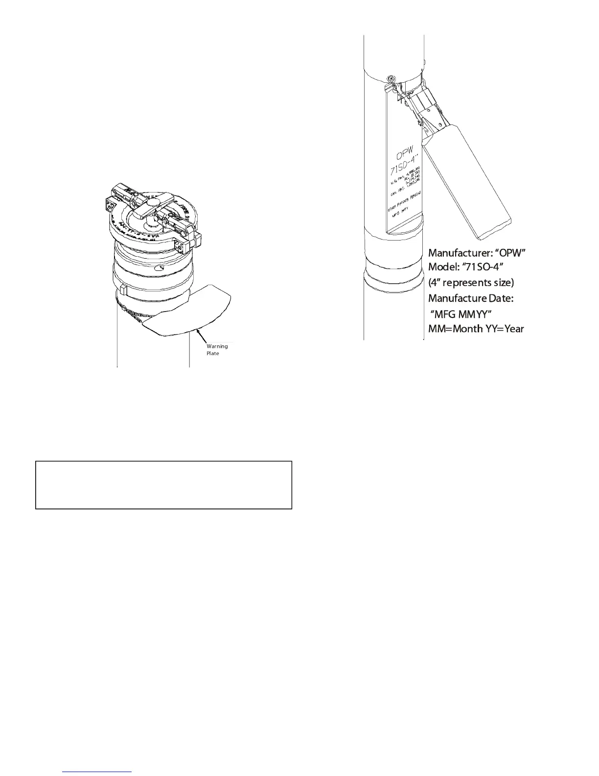
Figure 26 - Product Identication
 Loading...