EasyManua.ls Logo

Orban 622B - Page 19

Orban 622B
35 pages
Print Icon
To Next Page IconTo Next Page
To Previous Page IconTo Previous Page
Loading...
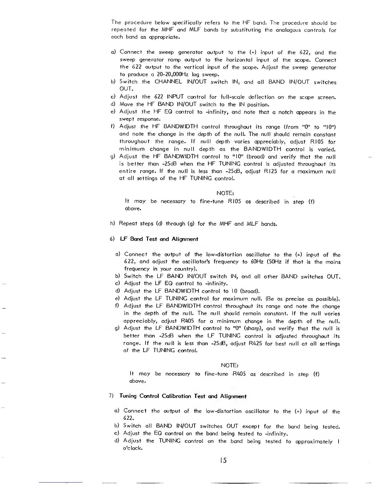
The
procedure below
specifically refers to
the
HF
band. The
procedure
should be
repeated
for
the MHF
and
MLF
bands
by substituting the
analogous controls
for
each band
as appropriate.
a)
Connect
the sweep generator
output to the
(+)
input
of
the
622,
and
the
sweep
generator
ramp output
to
the horizontal
input
of the scope. Connect
the 622
output
to the vertical input
of the
scope.
Adjust
the sweep
generator
to
produce a
20-20,
000Hz
log
sweep.
b) Switch
the
CHANNEL
IN/OUT
switch
IN,
and all
BAND
IN/OUT
switches
OUT.
c)
Adjust
the 622 INPUT
control
for full-scale deflection on
the scope
screen.
d)
Move the
HF
BAND IN/OUT
switch to the IN
position.
e) Adjust the HF
EQ
control
to -infinity, and note
that
a
notch
appears
in the
swept
response.
f)
Adjust the
HF
BANDWIDTH
control throughout
its range
(from
"0"
to
"10")
and
note the change
in the depth
of
the
null.
The
null
should remain
constant
throughout the
range.
If
null depth
varies appreciably,
adjust RI05
for
minimum
change
in null depth as the BANDWIDTH
control
is
varied.
g)
Adjust the
HF
BANDWIDTH
control
to
"10"
(broad) and
verify that
the null
is
better than
-25dB
when the
HF TUNING
control
is adjusted
throughout
its
entire
range.
If
the null
is less than
-25dB,
adjust RI25
for
a
maximum
null
at all
settings of the
HF TUNING
control.
NOTE:
It
may be
necessary
to fine-tune RI05
as described in
step (f)
above.
h)
Repeat
steps
(d)
through
(g)
for the MHF
and MLF
bands.
6)
LF
Band
Test
and
Alignment
a)
Connect
the output
of the
low-distortion
oscillator to
the
(+)
input of the
622,
and
adjust the
oscillator's frequency
to
60Hz
(50Hz if
that is the
mains
frequency
in
your
country).
b)
Switch
the
LF
BAND IN/OUT
switch
IN,
and all
other
BAND
switches OUT.
c) Adjust the LF EQ
control
to
-infinity.
d) Adjust
the
LF
BANDWIDTH
control to
10 (broad).
e) Adjust
the
LF
TUNING
control
for
maximum
null. (Be
as
precise
as possible).
f) Adjust
the
LF BANDWIDTH
control throughout
its range
and
note
the change
in the depth of the
null.
The
null should remain
constant. If the
null varies
appreciably,
adjust
R405
for a minimum change in
the depth
of the null.
g)
Adjust
the
LF
BANDWIDTH
control
to
"0"
(sharp), and verify that
the null is
better than -25dB when
the
LF TUNING
control is
adjusted throughout its
range. If
the null
is less than -25dB,
adjust R425
for best null
at
all
settings
of the
LF
TUNING
control.
NOTE:
It
may
be necessary
to fine-tune R405
as described
in step
(f)
above.
7)
Tuning
Control Calibration
Test
and Alignment
a)
Connect
the output
of the low-distortion
oscillator to the
(+)
input
of the
622.
b)
Switch
all BAND IN/OUT
switches OUT
except
for the
band
being tested.
c) Adjust
the
EQ
control on
the band being
tested
to -infinity.
d)
Adjust the TUNING
control on the
band being
tested
to
approximately
I
o'clock.
15

Related product manuals