**AWAJVMST$»C
EOUALIZ£«
«*owe»
Moost, «ia»o
Performance
Specifications
Specifications apply to each
channel
except as noted. All
specifications apply
when equalizer drives 600
ohm or higher
impedances. All noise
specifications
assume
a
20-20,000 Hz bandpass filter
with 18 dB/octave
Butterworth
skirts.
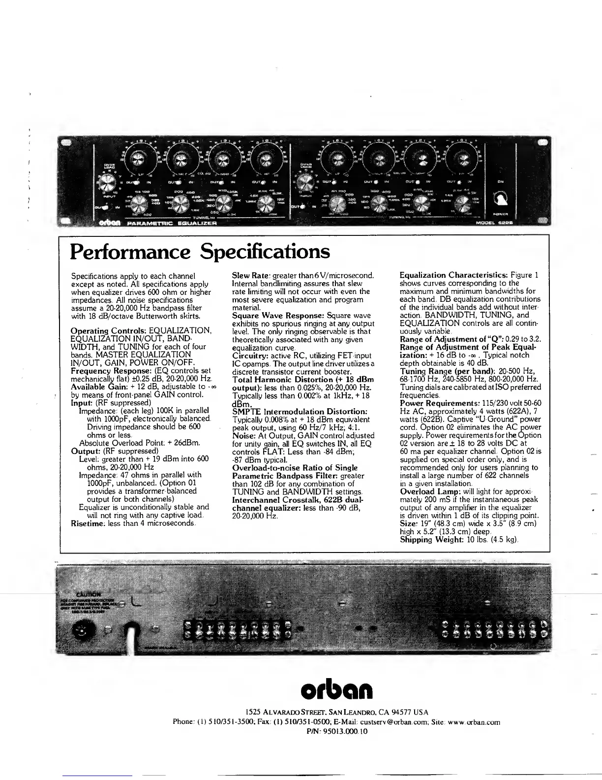
Operating
Controls:
EQUALIZATION,
EQUALIZATION
IN/OUT, BAND
WIDTH, and
TUNING
for
each
of four
bands.
MASTER
EQUALIZATION
IN/OUT,
GAIN,
POWER ON/OFF.
Frequency
Response: (EQ
controls
set
mechanically flat)
±0.25 dB,
20-20,000 Hz.
Available Gain:
+
12 dB,
adjustable
to
-
oo
by means of
front-panel
GAIN control.
Input: (RF
suppressed)
Impedance:
(each leg)
100K
in
parallel
with lOOOpF,
electronically
balanced.
Driving impedance
should be
600
ohms
or less.
Absolute
Overload
Point:
+
26dBm.
Output: (RF
suppressed)
Level:
greater than
+
19
dBm into 600
ohms,
20-20,000 Hz
Impedance: 47 ohms
in parallel
with
lOOOpF,
unbalanced.
(Option 01
provides a
transformer-balanced
output for both
channels)
Equalizer is
unconditionally
stable and
will not ring
with any
captive load.
Risetime:
less than
4
microseconds.
Slew Rate:
greater than 6 V/microsecond.
Internal
bandlimiting assures that slew
rate limiting will not occur
with even the
most
severe equalization and program
material.
Square Wave Response:
Square wave
exhibits no
spurious ringing at any output
level. The
only ringing observable
is
that
theoretically
associated with any given
equalization
curve.
Circuitry:
active RC, utilizing FET-input
IC opamps. The
output line driver utilizes a
discrete
transistor current booster.
Total
Harmonic Distortion (+
18 dBm
output): less
than
0.025%,
20-20,000
Hz.
Typically
less than 0.002% at 1kHz,
+
18
dBm.
SMPTE Intermodulation
Distortion:
Typically 0.008%
at
+
18 dBm
equivalent
peak output,
using
60
Hz/7
kHz;
4:1.
Noise: At Output,
GAIN control
adjusted
for unity gain, all EQ
switches IN, all EQ
controls FLAT: Less
than
-84
dBm;
-87
dBm typical.
Overload-to-noise
Ratio of Single
Parametric Bandpass Filter:
greater
than
102 dB for any
combination of
TUNING and
BANDWIDTH
settings.
Interchannel
Crosstalk, 622B dual-
channel equalizer: less
than
-90
dB,
20-20,000
Hz.
Equalization
Characteristics: Figure 1
shows
curves corresponding to the
maximum and minimum
bandwidths
for
each band. DB equalization
contributions
of the individual bands add
without inter-
action. BANDWIDTH,
TUNING, and
EQUALIZATION
controls are all contin-
uously variable.
Range of
Adjustment
of
“Q”:
0.29 to 3.2.
Range of
Adjustment of Peak Equal-
ization:
+
16 dB
to
-oo
.
Typical notch
depth obtainable is
40 dB.
Tuning Range (per band):
20-500
Hz,
68-1700 Hz,
240-5850
Hz, 800-20,000 Hz.
Tuning dials are calibrated at ISO
preferred
frequencies.
Power Requirements: 115/230
volt
50-60
Hz
AC,
approximately
4 watts (622A),
7
watts (622B).
Captive “U-Ground” power
cord. Option 02
eliminates the AC power
supply. Power
requirements for the Option
02
version
are ±
18 to 28 volts DC at
60 ma per
equalizer channel. Option 02 is
supplied on
special order only, and is
recommended only for
users planning to
install a large
number of 622 channels
in a
given installation.
Overload
Lamp:
will light for
approxi-
mately 200 mS if the instantaneous peak
output of any amplifier in the
equalizer
is driven within 1 dB of
its clipping point.
Size:
19"
(48.3 cm)
wide
x
3.5"
(8.9
cm)
high x
5.2"
(13.3 cm) deep.
Shipping
Weight: 10 lbs.
(4.5
kg).
f-
m
if* -rn
%
<
'4* i
'
*
'C/.,
.........
ty
,f>
^ ^
i.#
1
3
§
t
<3
%
%
%
9
Ofbcifl
1525
Alvarado Street. San
Leandro, CA
94577
USA
Phone:
(1)
510/351-3500;
Fax:
(1)
510/351-0500;
E-Mail: custserv@orban.com;
Site: www.orban.com
P/N: 95013.000.10
 Loading...