All ORCA products are manufactured in accordance with the highest quality
standards. ORCA guarantees this product
to be free from defects in materials or workmanship for 60 days from the
original date of purchase verified by sales receipt. This limited warranty does
not cover damages resulting from abnormal wear, misuse or improper
maintenonce of the product.
To avoid unnecessary service and mailing charges, always eliminate all other
possibilities and check all components for malfunctions before sending in your
unit for repair. Products sent in for repair that operate perfectly will be charge a
service fee.
When sending in the product, always pack carefully and include the original
sales receipt, a description of the problem encountered, your return address
and contact information. Since we do not have control over the installation and
use of this product, we cannot accept any liability for any damages resulting
from the usage of this product. Therefore, using this product is at your own risk,
and the user accepts all resulting liability from installing and using of the
product.
Copyright@2021 . All Rights Reserved.
Images may not be used without permission.
Instruction Manual
Version 1.4
Thank you for choosing ORCA Products. Welcome to the power and convenience
of Brushless RC. By purchasing the BP1001 Competition Brushless Electronic
Pro Blinky Speed Control ("ESC") you have chosen one of the most advanced
speed controls in RC Racing. The BP1001 allows customization for multiple
programmable parameters and the only one ORCA speedo can used the buttonin
esc without program card to programmale the esc. (If using the ESC's Program
Card which can be purchased separately).
Please read this manual thoroughly to familiarize yourself with the installation,
setup and operation. By operating this product, you accept the ORCA Warranty
*** 32 bit processor *** Low resistance FET
*** Continuous current *** Auto Fan control
System: Brushless
Forward/Brake/Reverse: Yes (Factory preset at Forward/Brake)
Dimensions: 30.45(L) x30.35(W) x mm
Weight: (excluding wires)
Voltage Input: 6V-11V
Peak Current: 380A
Continuous current : 100A
Motor Limit: Over 10.5Turns
Motor Type: Sensored 540 sized brushless motors
B.E.C.: 4A_6V
Multi Protection System: Yes
10.35(H)
20.80g
Specification
+
-
Lipo battery
8.4V
Capacitor
ABC
+
A
+
-
C
B
Receiver
CH4
CH3
CH2
Ch1
(BEC cable)
CoolingFan
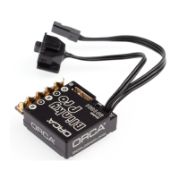
Installation & Connectors
+Red
-Black
-Black
+Red
A
B
C
+
Red
Sensor cable
* Connect the sensor cable between the ESC sensor plug and the Motor sensor plug.
* Connect the receiver plug to the CH2/throttle pin of the receiver.
* Secure the on/off switch in a place where it will not be accidentally knocked to the
¡§off¡¨position during a crash.
* The Fan port voltage is drawn directly from the battery.
*
Radio & Esc setup
Transmitter Settings:
Initialset-upofthethrottleend-pointsoftheESC:
Note!
Throttle Travel Maximum / 100%
Brake Travel Maximum / 100%
Throttle Exponential Start with 0%
Throttle Neutral Trim Center / 0
Throttle Servo Reverse Reverse (Futaba, KO, Sanwa)
* Connect the power wires of the ESC to a fully charged battery set; making sure the
polarity is correct.
* Bind your receiver and transmitter first if your radio requires you to do so.
* Turnonthetransmitterandholdthethrottleatfullbrakeposition.
* Turn on ESC and listen for 2 beeps.
* After you hear the 2 beeps, apply full throttle and listen for another 2 beeps.
* Once you hear the 2 beeps, release the throttle to neutral position.
* A beep will then sound, signifying that the ESC endpoints have been successfully
set.
If you do not hear the beeping sound as described above, try reversing the throttle
reverse setting in the transmitter.
Customizing the Esc
Due to the different requirements of each style and class of racing, it is important to
customize your ESC for each use case. Customization of the ESC is done using the
Program Card (Sold Separately):
To begin, connect the battery wires to a charged battery, then connect supplied 4pin
wire (200mm) to the ESC setting port (4pin port) and Program Card. Turn on the ESC
and the Program Card will activate automatically. Note that the screen will show
"Loading…” during initialization -indicating that the ESC is copying the current setup in
the ESC to the Program Card. Once loading is completed, the screen will show "ETS
Blinky Pro" and "Program". You can now begin programming your ESC.
Press "Enter" to access Program Mode.
Whenever in doubt, double check your ESC setting by initializing the Program
Card again and checking each menu setting.
Navigation around the Program Menu is done using the 4 buttons on the right hand side
of the Program Card. The function of each button varies depending on which screen the
display is showing:
"Select" button------------------------go to next select
PressandHold"Select" button two second -------go to back page
" " button - Scroll up
" " button - Scroll down
"Enter" button - Send Changes from Program Card to the ESC
and overwrite old data in the ESC
The Program Card is not included and is sold separately.
The Program Card will compare the Parameters within the card and ESC before
sending. If changes are detected, you will hear a series of beeps and the Program Card
will display:
TIPS!
NOTE!
TIPS! Do not worry about making mistakes. You will not damage the ESC during setting.
If in doubt, you can always reload the default set up and start over again.
Operation
Getting started
Turn on the on/off swithch, the screen will display:
ETS BlinkyPro
1: Program
Send Succes
Bec cable
Use " " button and " " button to find [Program], [Data Record] or [Update].
Press " " button to choose. Each mode presented are independent from each other
and will require setup.
Press "SELECT" button for 2 seconds to go back to the previous screen.
ETS Blinky Pro
3: Update
ETS Blinky Pro
2: Data Record
ETS Blinky Pro
1: Program
2. Data Record
.
Double press "Enter" button to clear the data, otherwise Min and Max data will keep
Forever.
Battery voltage Esc Temperature
T hrottle position Motor rpm
1. Program
Enter direct go to setup page,
Use "SELECT" button go to next setup item
"2:BatteryCutOff" or "3:Punch or 4-10.
Press" "button
Battery min voltage Max Esc Temperature
Max motor rpm
A+B-C must match the Initial Setup
.( Improper configuration may damage the ESC.)WARNING!
Existing:
Record the last:
ABC
+
S
+
-
AA
+
-
C
B
A+B-C
+RED
-BLACK
1:RunningMode
Forward/Brake
8.38V Tesc: 35
1.35ms 0rpm
7.62V MAX E 95
RPM:48370
3. Update
Updating of ESC Firmware:
Preparing the SD card for use:
* Scroll to the "Update"menu and press "Enter". This will show the current ESC
Firmware Version.
* Press "Enter" again to access the SD cards Firmware folder. Select the firmware
Version that you would like to use to update the ESC. Press"Enter" again and the
update will commence (It will take around 1 minute to complete the update).
* Depress and hold the Program card "Enter" button while turning on the ESC. It will
display the current Program card firmware Version.
* Press "Enter" again to access the SD cards Firmware folder. Select the Firmware
Version that you would like to use to update the Program Card. Press "Enter" again and
the update will commence (It will take around 1 minute to
complete the update).
Format a microSD card using FAT32 file structure using a personal computer. If you are
using a Micro SD Card larger than 32GB, you will need to use a 3rd party SW Package
to do this. Create a new folder called "Firmware". Download the latest firmware from
www.orcarc.com/firmware/ and copy the file to the "Firmware" folder on the Micro SD
card. Once completed, install the MicroSD card into the microSD card slot of the
Program Card. Both the Program Card and ESC Firmware Files need to be copied in to
the "Firmware" Folder. A maximum of 10 of each ESC/Program card firmware can be
present in the folder at any one time.
OR
Updating of Program Card Firmware:
ETS BlinkyPro
Limite13.5T-1.1
Multi Protection System -- In addition to the Low Voltage and Overheat
Protection that were described above, the ESC is protected in 2 more ways.
* The motor have not temperature protection in this esc but the ESC is
protected against damage when the motor is stuck and does not turn at all.
Power will not be applied in this situation.
* CAUTION! Since the ESC relies on the feed back of the 3 motor wires to
deploy this protection, it ONLY works if the motor does not turn AT ALL. If the
rotor has any rotation, the ESC will consider the motor to be operational and
the power to the motor will not be cut off.
* In case the radio signal to the ESC is interrupted for over 1 second during a
run, the ESC will cut off until the signal resumes.
Firmware Limit 13.5T - 1.1 blinking red LED two times.
Firmware Limit 17.5T - 1.1 blinking red LED three times.
* Connect the ESC to the battery pack only when you are ready to run. This
will avoid draining the battery pack. Always disconnect the battery after your
run.
* A small spark may occur when the battery is initially connected to the ESC.
This is normal and is due to the charging of the capacitors.
ESC auto temperature protect
*
Motor Lock Protection:
Fail Signal Protection:
LED Blinking:
ETS Blinky Pro ESC
Misc. Tips:
The esc will auto down power to 50% when the esc temperature over 125F
degree
Operating Tips
* Install/Solder the relevant battery connector (Battery Specific) to the battery wires.
Red to+veandBlackto-ve.(
)
* Connect supplied BEC wire(150mm) to 3pin port match the (- + s) between the
receiver connector and ESC.
* Connect the 3 motor wires to the motor; you can either solder the wires directly to the
motor or use your favorite connectors. Match the label of the ESC Output (A, B, C) to
the Tablabels on the motor when soldering. Avoid soldering each joint for longer than
5 seconds. Prior to operation make sure you have not created a short by either
creating a wire bridge or solder bridge on the solder tabs on the motor. (
Improper wiring may damage the ESC and void the warranty.)
WARNING!
WARNING! Reversing the battery polarity will destroy
your ESC and void the warranty.
B
P1001
B
P1001
SET
B
P1001
OFF ON
Power Switch
ETS BlinkyPro
Limite17.5T-1.1