Do you have a question about the Oregon Scientific RAR188A and is the answer not in the manual?
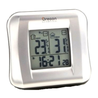
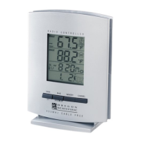
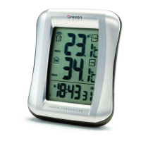
Overview of the main unit's LCD display features and available controls for operation.
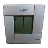
Diagram illustrating the main unit, highlighting its components and controls for operation.
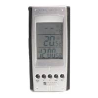
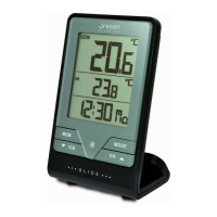
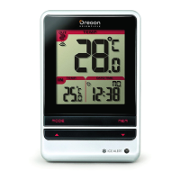
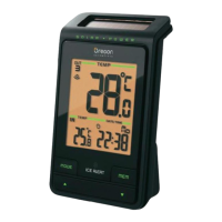
Diagram of the remote sensor, identifying its parts and features for outdoor temperature monitoring.
Instructions for inserting batteries into the main unit and remote sensor for initial power.
Steps to prepare and set up the remote sensor, including battery insertion and channel selection.
Process to initiate signal transmission between the remote sensor and the main unit for data reception.
Manual steps to set the current time, date, and language on the main unit.
How to switch between different clock display modes, such as showing seconds or weekdays.
Procedures to set and activate dual alarm functions, including time and on/off status.
Explanation of the indicators that show when alarms are set or active.
Details on the temperature information displayed, including current, min/max readings, and trend.
Instructions on how to clear stored minimum and maximum temperature records.
Explanation of the trend indicator showing if temperature is rising, steady, or falling.
Essential safety guidelines and warnings for proper use and handling of the device.
Guidance on how to clean the product using a damp cloth and mild detergent.
A guide to diagnose and resolve common operational problems with the thermometer.
Technical specifications for the main indoor unit, including dimensions, weight, and power requirements.
Technical specifications for the remote outdoor sensor, including dimensions, weight, and battery type.
Details on operating temperature ranges, RF frequency, transmission range, and channel support.
Information regarding FCC compliance, operating conditions, and interference guidelines for the device.
The Oregon Scientific™ Wireless Indoor / Outdoor Thermometer with Dual Alarm Clock (RAR188A) is a versatile device designed to provide precise time-keeping, dual alarm functionality, and temperature monitoring. It comes with a main unit and a remote sensor (THN122N), with the option to connect up to three THN122N remote sensors for additional data collection (additional sensors sold separately).
The main unit features an LCD display that shows the current time, day of the week, date, and dual alarm settings. It also displays indoor and outdoor temperatures, along with a temperature trend indicator to show if the temperature is rising, steady, or falling. Battery indicators for both the main unit and remote sensor alert users when batteries are low. The device includes two independent alarms, each with a 2-minute crescendo alarm. The remote sensor collects temperature data and transmits it wirelessly to the main unit.
| Brand | Oregon Scientific |
|---|---|
| Model | RAR188A |
| Category | Thermometer |
| Language | English |