RevivalDRIVE Switcher Interface User Guide
Page 2 of 4
Introduction
The RevivalDRIVE Switcher Interface allows a remote switching system, such as the GigRig G2 or Boss
ES-8, to remotely toggle the following functions on the RevivalDRIVE pedal:
Active channel
Bypass state
Mid engage
Blend override functions
The unit works by converting the four latching control switches to the combination of latching and
momentary switching used by the RevivalDRIVE.
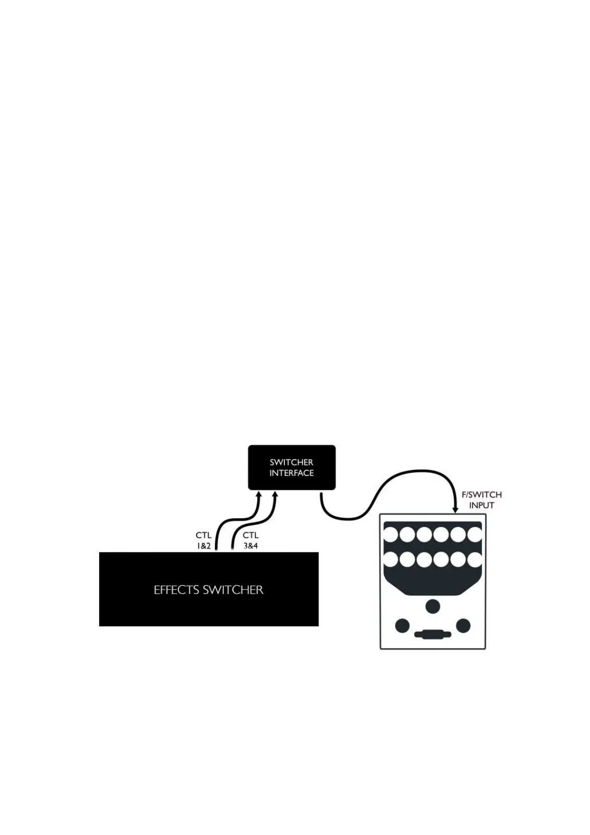
Connecting the Switcher Interface
Using standard TRS jack cables, connect INPUT A and INPUT B to your switching system’s latching
switch (CTL) outputs.
Connect OUTPUT on the Switcher Interface to the F/SWITCH input on the RevivalDRIVE, using a 1/4”
TRS jack cable.
Connect a regulated 9V power supply with a 2.1mm centre-negative connector power to the 9VDC IN
socket. Powering additional devices from the 9VDC THRU will increase the overall current draw, be
careful not to exceed the rating for your power supply.
NOTE: Remote switching of the bypass state and active channel can only be achieved with the Switcher
Interface. The interface converts latching control formats to a short momentary pulse. In the unlikely
event of power loss, the user may find that switcher-to-pedal synchronisation is lost. To re-sync the set-
up the user should toggle the affected function directly on the pedal, by pressing the appropriate
footswitch.