IG-183-EN version 06; 31/03/2020
59
General instructions
cgm.3 system: medium voltage SF
6
gas-insulated
cubicles up to 38 kV according to IEEE and CSA standards
Recommended sequence of operations
5.8. Fuse replacement sequence
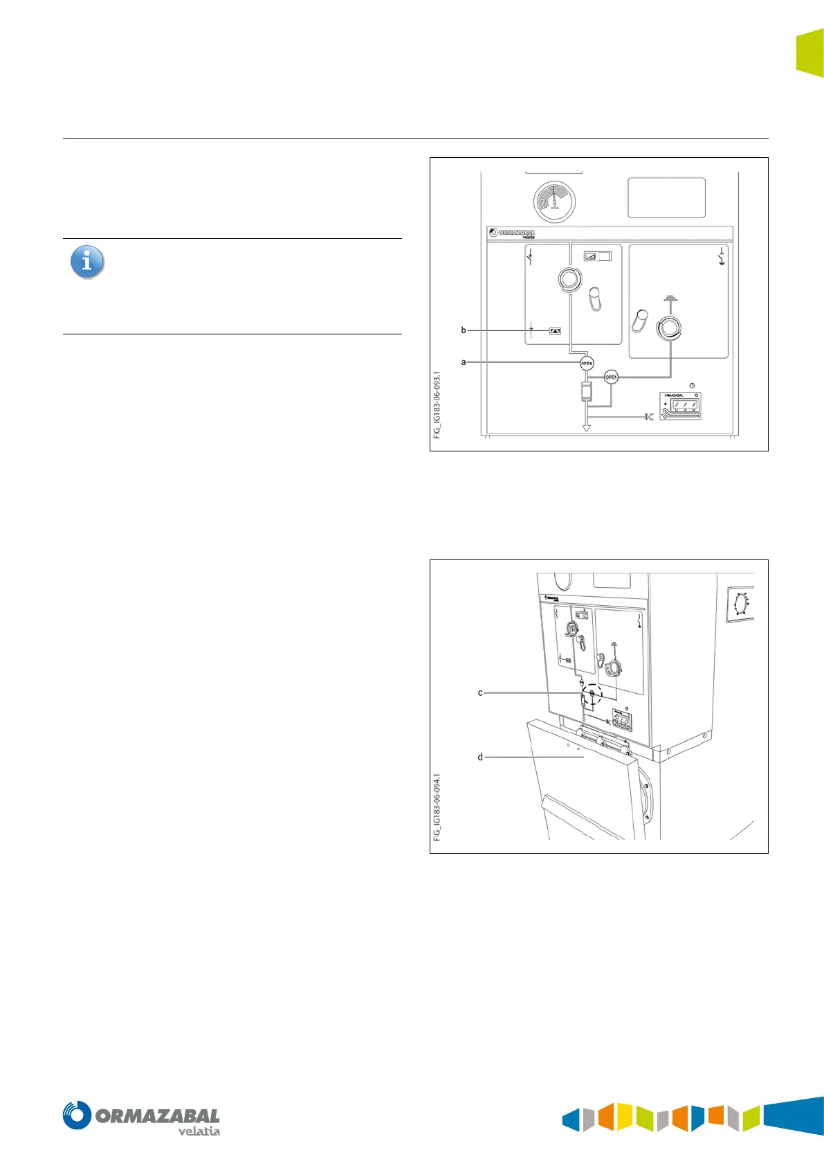
If any of the 3 fuses blows, the switch-disconnector (a) will
open automatically; this is indicated by the red position
indicator (b) located on the front of the driving mechanism
compartment.
As an option, an auxiliary blown fuse indication for any
of the 3 fuses is also available. More precisely, it consists
of a normally open contact (NO) plus a normally closed
contact (1NO + 1NC) for auxiliary circuits, such as an
illuminated indication showing that any of the fuses
has blown.
Figure 5.22. Fuse tripping indication in cgm.3-p
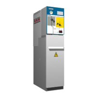
In order to replace the fuses, the following procedures must
be followed:
1. Close the grounding switch (c).
2. Remove the cable and fuse compartment access cover
by pulling the handle (d) up.
Figure 5.23. Opening the cable compartment cover