EasyManuals Logo

Orolia GSG-8 Series User Manual

Orolia GSG-8 Series
18 pages
To Next Page IconTo Next Page
To Previous Page IconTo Previous Page
Page #7 background imageLoading...
Page #7 background image
orolia.com GSG-8 Getting Started Guide | 7
4. Inputs and Outputs
Rear Panel Connectors
Sections are identified from left to right. Connectors are identified from top to bottom, left to right.
Power Section:
AC power
Input
Graphics Card Section:
(4) DP port (RTX 5000 Graphics Card)
Outputs (4)
(1) USB port (RTX 5000 Graphics Card)
NOT SUPPORTED
Communication Section:
VGA port
Output
(2) Ethernet ports
Input/Output
(2) USB 2.0 ports
Input/Output
(4) USB 3.0 portss
Input/Output
CDM-5 Card:
(5) PPS
Output
PPS
Input
10 MHz clock
Input
(5) 10 MHz clock
Output
DTA-2115B Card:
50 ohm SMA RF
Output
75 ohm BNC RF
Output
10 MHz clock
Input
PPS
Input
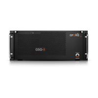
Front Panel Connectors
Found inside the front panel cover.
(2) USB 2.0 port
Input/Output

Questions and Answers:

Question and Answer IconNeed help?

Do you have a question about the Orolia GSG-8 Series and is the answer not in the manual?

Orolia GSG-8 Series Specifications

General IconGeneral
BrandOrolia
ModelGSG-8 Series
CategoryReceiver
LanguageEnglish

Related product manuals