6
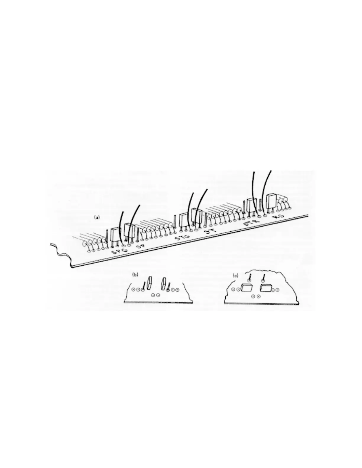
Fig. 1. Input Polarity Jumper Selection for (a) Factory-Set Input Positions, (b) Inputs Set in Negative Position, and (c) Input Set in
Positive Position.
Polarity
Input Jumper Label
Start ST
Stop SP
Start Gate STG
Stop Gate SPG
Reset/Inhibit RS
Ext/Strobe STA
4. Refer to Fig. 1 to locate the jumper to be
changed on the 567.
5. Using a pair of pliers, remove the small blue
jumper selected and reconnect it as shown in
Fig. 1 for either positive or negative polarity.
6. Reinstall side Cover.