11
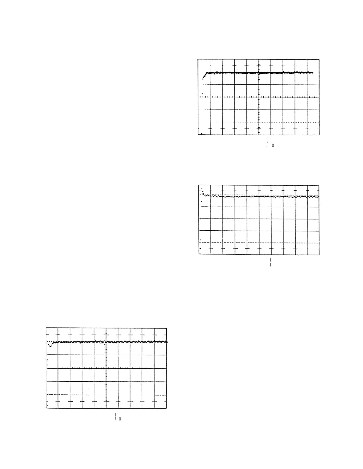
Range = .1
Multiplier = x100
$
1µs
(Vert): Full Scale = 5 x 10 counts
4
(Horiz): Full Scale = 105% range
Fig. 6. Differential Linearity for the Indicated Ranges.
Range = .1
Multiplier = X1
#
100
(Vert) : Full Scale 5 x 10 counts
4
(Horiz) : Full Scale = 105% range
Range = .1
Multiplier = X1
$
100ns
(Vert): Full Scale 5 x 10 counts
4
(Horiz): Full Scale = 105% range
1. Set the delay for the stop signal at about 400 ns.
2. Set the 567 time range for 500 ns.
3. Use the internal strobe mode for the 567. Adjust
the oscilloscope sweep as required to identify
the TAC output pulses.
4. Adjust the delay for the strobe signal >500 ns to
ensure that it will occur later than the full time
range.
5. Switch the 567 to its external strobe mode and
observe the TAC output pulse. It should be
identical to the pulse observed in step 3 except
for the time at which it occurs.
6. Vary the strobe delay and observe that there is
no change in the TAC output amplitude but that
the output delay follows the strobe delay.
TESTING THE SINGLE-CHANNEL ANALYZER
The SCA can be tested by the following procedure:
1. Use the circuit shown in Fig. 2. Select a
convenient time range and adjust the stop delay
to obtain an output of ~5V through the TAC
Output connector.
2. Set the lower-level discriminator dial at 4.0 and
the window-level discriminator dial at 2.0.
Change the stop delay to change the TAC
output pulse amplitude from 3V to 7V. Note that
the SCA output pulse is present only when the
TAC output amplitude is within the range of 4 to
6V.
5.2. CORRECTIVE MAINTENANCE
Clean the surfaces of the printed circuits, the
connectors, and all chassis parts periodically to
prevent accumulated dust from forming leakage
paths between the circuit components.
If the instrument is suspected of malfunctioning,
use the performance tests of Section 5.1 to aid
verification. When incorrect operation is identified,
disconnect the 567 from its position in the system
and perform routine diagnostic tests with a pulse
generator and an oscilloscope. Use the timing chart
in Fig. 7 to isolate the problem, and use schematic
diagram 678890 at the back of this manual to
localize the malfunctioning.