10
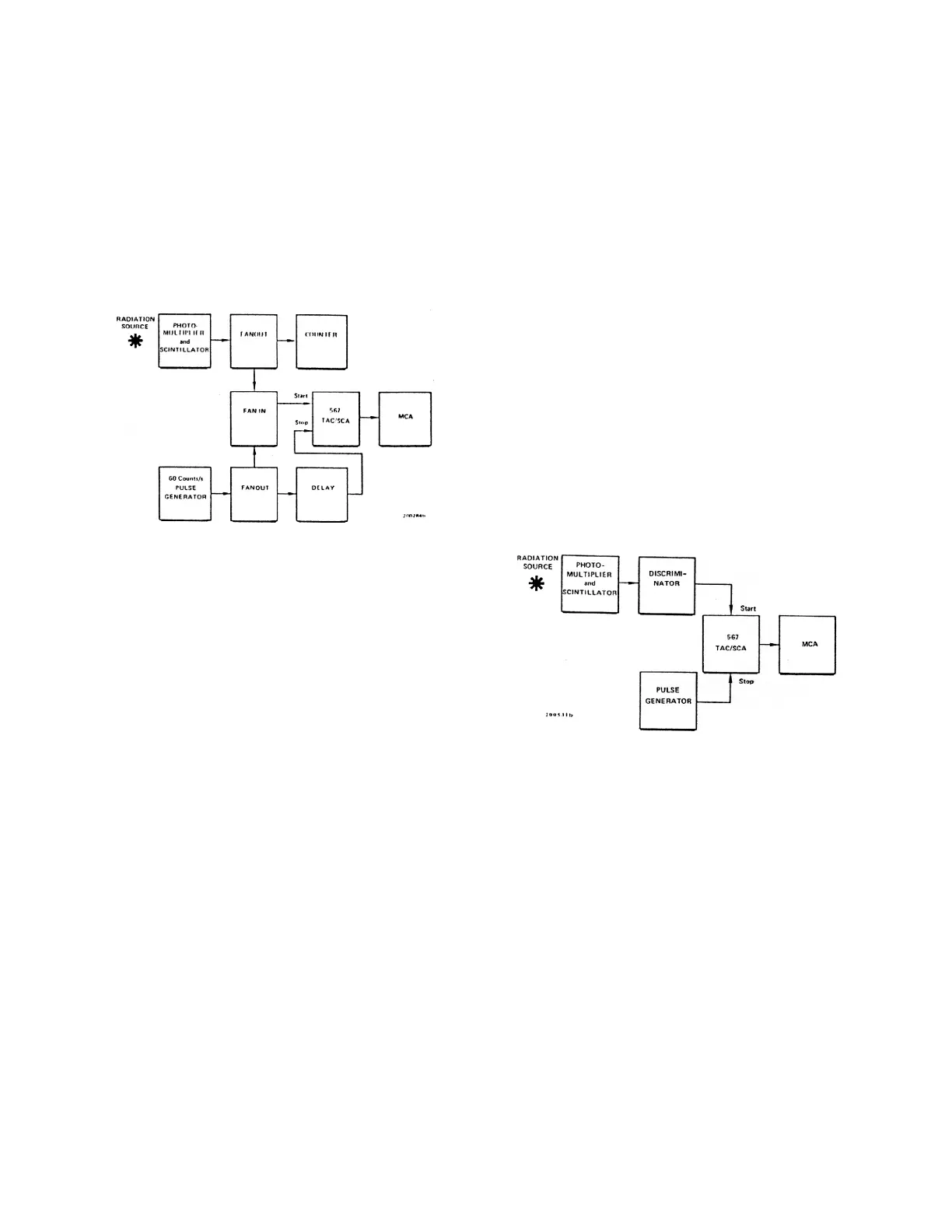
Fig. 4. Test system for Checking Count Rate.
Fig. 5. Test System for Checking Differential Linearity.
The following test, based on the system connection the count levels for each channel of the MCA
shown in Fig. 4, permits accumulation of a basic should be equal. After the test has been run long
timing spectrum for the start-stop input pulses at 60 enough to assure statistical accuracy (e.g., >25,000
Hz. As the external count rate for start only is counts/channel), the spectrum should be similar to
increased by regulating the random pulse those illustrated in Fig. 6. Any deviation from a
generator, the internal pulse rate in the 567 is straight line represents a differential nonlinearity,
increased, and a ratemeter will monitor the resulting and the percent of deviation is the difference
rate at which the internal capability is impaired. between this count level and the average divided by
1. The photomultiplier may be used as a random
pulse generator, triggered by a radiation source.
Use an initial sensitivity setting above the
energy level for a zero output pulse rate.
2. Adjust the delay for the stop input to ~0.4 µs.
3. Select the 0.5 µs time range with the 567.
4. Adjust the system for a timing spectrum
accumulated for the 60-Hz input pulses.
5. Decrease the threshold of the discriminator to 3. Operate the system and monitor the dead-time
generate random start signals with no meter on the MCA. Regulate the random start
corresponding stop signals. Monitor the random rate to cause the MCA dead time to be ~10%.
rate with the ratemeter.
6. Observe the timing spectrum as the random system until the average count level stored in
input rate is gradually increased. Watch for each channel is sufficient to ensure statistical
interference in the accumulated spectrum. accuracy.
DIFFERENTIAL LINEARITY MEASUREMENTS
A
system for testing differential linearity of the 567 is
shown in the block diagram in Fig. 5. In this system
the random pulse generator is used as the source
for start signals, and a pulse generator with a fixed
rate is used for stop signals. The measurable time
interval between a start and stop is a random value,
with equal probability that it will be any time system for checking the external strobing mode is
difference up to the periods between the regular shown in Fig. 7. This system can be used to verify
stop signals. For an infinite number of 567 outputs the principles of operation of the 567.
the average count level.
1. Select the 567 time range to be tested.
2. Calculate the maximum stop pulse repetition
rate for the selected time range. This should be
slightly lower than the reciprocal of the time
range. For example, for the 1 µs time range the
reciprocal is 1 x 10 , and a pulse generator rate
6
of 4 to 5 times 10 should be satisfactory. A
6
lower rate increases the time required to run the
test, while a faster rate will reduce the window
level response because of MCA dead time.
4. Clear the analyzer to zero and operate the
5. Compare any nonlinearity indications to the
specifications listed in Section 2. Some
nonlinearity can be expected in channels in the
lower 5% of the MCA range as shown in Fig. 6
because of the stop pulse width and the TAC
gating time.
CHECKING EXTERNAL STROBING MODE
The