9
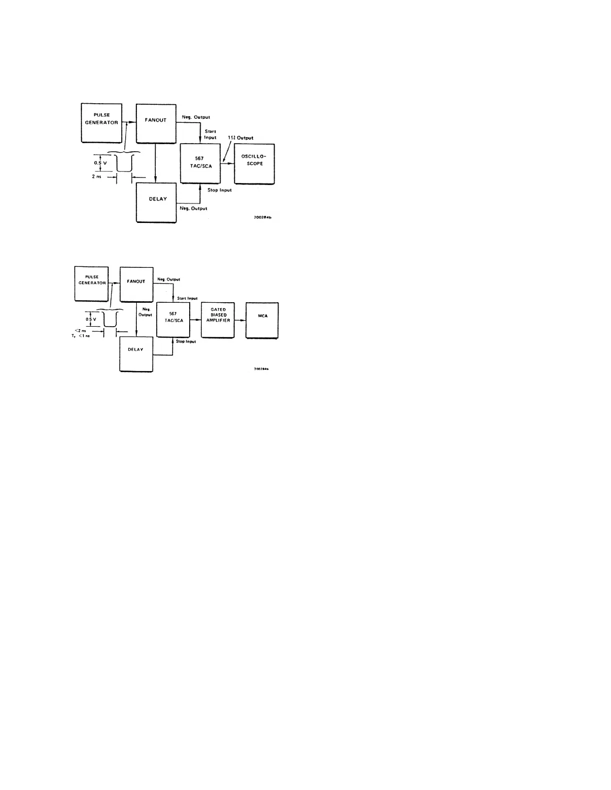
Fig. 2. Test System for Checking Conversion.
Fig. 3. Test Systems for checking Converter Resolution.
RESOLUTION TESTS
See Fig. 3 for the typical
test setup used for resolution checks. The start and
stop pulses used for this test must have fast rise
time and be jitter-free. The minimum delay
recommended for the stop pulses is 15 ns. The
resolution of any scale can be measured with this
setup, and the main consideration is that each stop
signal delay be within the linear region of the
selected time range. The testing procedure consists
of the following:
1. Adjust the delay for the stop input to basic
setting of 30% to 80% of the selected time
range.
2. Operate the system and obtain a timing
spectrum. Normalize the output amplitude full
range for the normally digitized full range of the
ADC in the analyzer.
3. After you have accumulated an adequate
spectrum to assure statistical accuracy of
photopeak measurements (~1000 counts in the
peak channel), identify the peak channel
number and measure the FWHM channel
number limits. Log for reference.
4. Increase the delay for the stop signal by a fixed
and known amount. This may be done by
switching in a fixed delay line cable (ORTEC
425A) or by careful adjustment of the delay unit
controls. The total delay for the stop signal must
still be <100% of the selected time full range.
5. Accumulate a spectrum for this measurement of
increased time intervals.
6. Observe the relocated photopeak in the timing
spectrum and record its peak channel number
and its FWHM channel number limits.
7. Subtract the peak channel number in step 3
from the peak channel number in step 6. This is
the number of channels that represents the time
variation injected at step 4.
8. Using the formula below, calculate time
resolution effective for the established system
calibration:
>t per channel = stop delay increase : channel
shift
9. With the equation below, calculate the converter
resolution using the FWHM channel width from
either step 3 or step 7. These widths should be
the same at either peak location.
Time resolution (FWHM) = FWHM channel width
x>t per channel.
This resolution is affected adversely by any jitter
that may be present in the discriminator and by the
resolution of the amplifier. Allowances should be
made for these contributions.
COUNT RATE TESTS
In many applications it is
important for a time-to-amplitude converter to
handle high count rates, both external and internal.
Since the start input is gated internally and the
conversion circuits are all direct-coupled, the limit
for its external count rate capability is determined
solely by the input pulse width, and there are no
pileup effects. The limit on the internal count rate is
imposed by the conversion and reset process,
where the start input is disabled through a converter
busy interval following each accepted start signal.
A converter busy interval is the measured time plus
1 µs for start- stop intervals within the selected time
range for X1 and X10 multiplier, 5 µs for X100, and
50 µs for X1k and 10k multipliers.