12
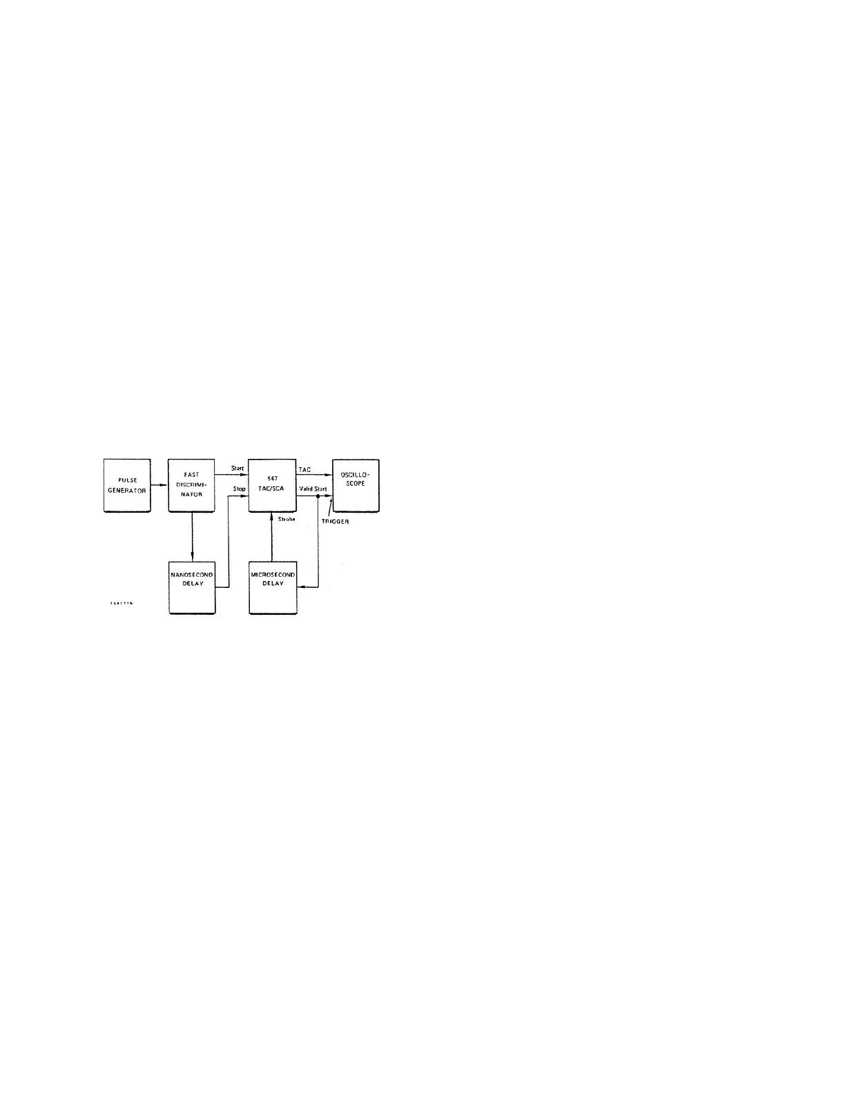
Fig. 7. Test System for Checking External Strobing Mode.
CALIBRATION
Three critical calibrations that may
need to be made are described:
Output Offset Calibration
Potentiometer R223,
located on the printed wiring board (PWB), adjusts
the dc offset voltage of the TAC output over a ±85
mV range. To calibrate the output offset, connect
power to the 567 with no input signal connections.
While monitoring the dc voltage at the TAC output,
adjust R223 to obtain 0 V dc.
Conversion Current Calibration
This calibration
affects the conversion gain of the TAC circuitry. To
calibrate the conversion gain of the 567, set up the
circuit as shown in Fig. 2, and follow the setup
procedures outlined in steps 1 through 3 of
Section 5.1, “Conversion Tests.”
1. Adjust PWB-mounted potentiometer R128 fully
counterclockwise. A TAC output pulse of ~8.5 to
9.8V should be present at the TAC output.
2. Adjust R128 clockwise until the output pulse
reaches +10V and begins to half-fire.
3. Turn R128 slightly in the counterclockwise
direction until the TAC output is solid or full-firing.
Output Width Adjustment
Leave the system
connected as described above. TAC output pulse
width may be adjusted over a range of 1 to 3 µs via
PWB-mounted potentiometer R163. Factory-
adjusted width is nominally 2 µs.
5.3. FACTORY REPAIR
This instrument can be returned to the ORTEC
factory for service and repair at a nominal cost. Our
standard procedure for repair ensures the same
quality control and checkout that are used for a new
instrument. Always contact the Customer Service
Department at ORTEC, (865) 483-2231, before
sending in an instrument for repair to obtain
shipping instructions and so that the required
Return Authorization Number can be assigned to
the unit. Write this number on the address label and
on the package to ensure prompt attention when it
reaches the ORTEC factory.