AC input in 3K model for safety operation.
Step 3: UPS output connection
For socket-type outputs, there two kinds of outputs: programmable outlets and general
outlets. Please connect non-critical devices to the programmable outlets and critical
devices to the general outlets. During power failure, you may extend the backup time to
critical devices by setting shorter backup time for non-critical devices.
For terminal-type input or outputs, please follow below steps for the wiring configuration:
a) Remove the small cover of the terminal block
b) Suggest using AWG14 or 2.1mm
2
power cords. Suggest using AWG12-10 or
3.3mm
2
-5.3mm
2
power cords for NEMA type.
c) Upon completion of the wiring configuration, please check whether the wires are
securely affixed.
d) Put the small cover back to the rear panel.
Step 4: Communication connection
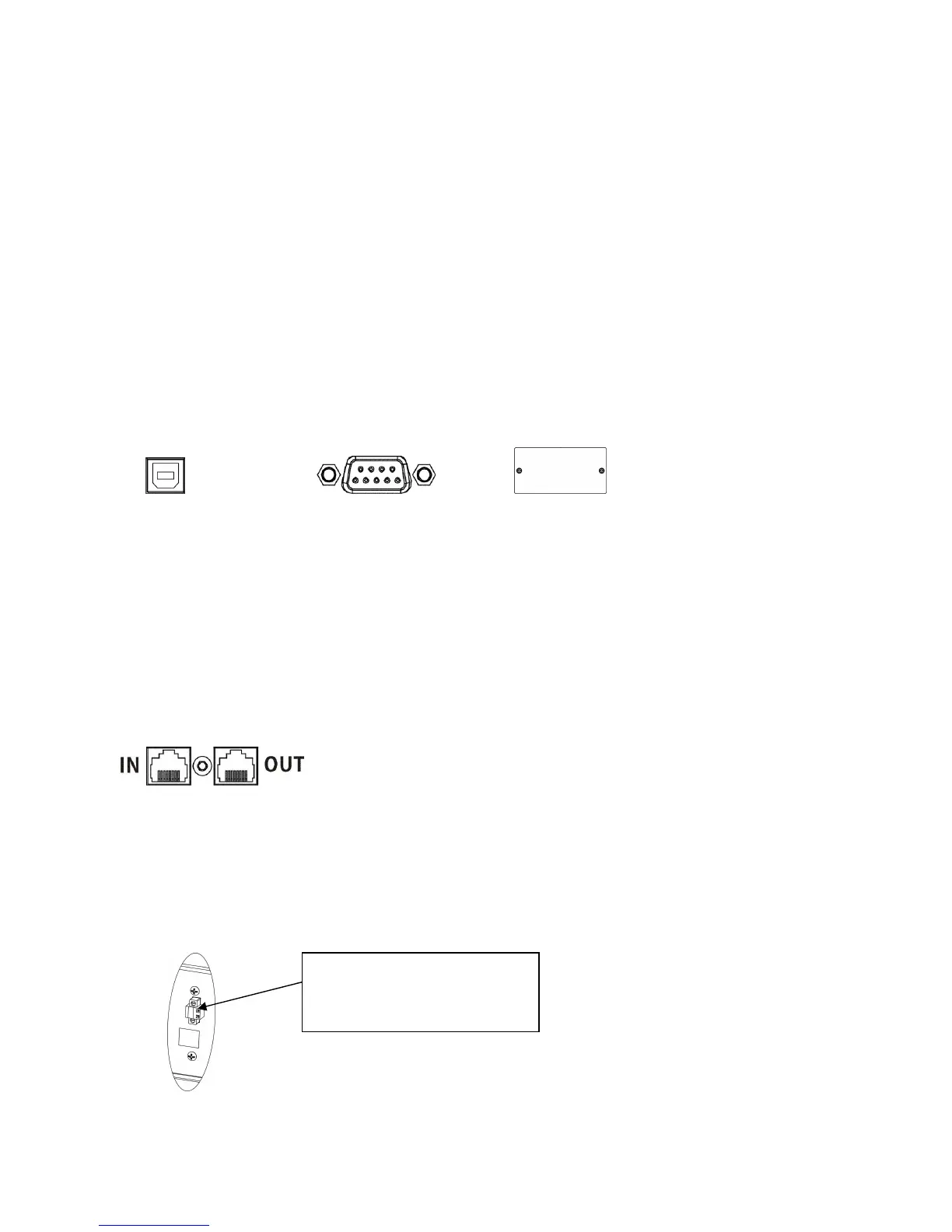
Communication port:
USB port RS-232 port Intelligent slot
To allow for unattended UPS shutdown/start-up and status monitoring, connect the
communication cable one end to the USB/RS-232 port and the other to the communication
port of your PC. With the monitoring software installed, you can schedule UPS
shutdown/start-up and monitor UPS status through PC.
The UPS is equipped with intelligent slot perfect for either SNMP or AS400 card. When
installing either SNMP or AS400 card in the UPS, it will provide advanced communication and
monitoring options.
PS. USB port and RS-232 port can’t work at the same time.
Step 5: Network connection
Network/Fax/Phone surge port
Connect a single modem/phone/fax line into surge-protected “IN” outlet on the back panel of
the UPS unit. Connect from “OUT” outlet to the equipment with another modem/fax/phone line
cable.
Step 6: Disable and enable EPO function
Keep the pin 1 and pin 2 closed for UPS normal operation. To activate EPO function, cut the
wire between pin 1 and pin 2.
It’s in closed status for UPS
normal operation.