THE ORVIS COMPANY | MANCHESTER VERMONT 05254 | www.orvis.com
Orvis Technical Questions: info@orvis.com or 800-778-4778
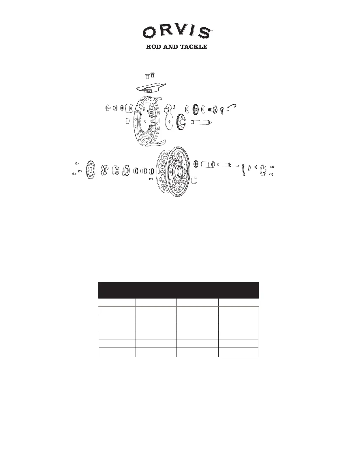
CFO
REEL ASSEMBLY
1 Drag Screw
2 Drag Nut
3 Drag Washer
4 Drag Knob
5 Spindle Cap
6 Reel Body
7 Reel Foot Screws
8 Reel Foot
9 Clicker Retainer
10 Clutch Gear
11 Rulon Drag Washer
12 Drag Gear
13 Rulon Drag Washer
14 Drag Gear Cap
15 Clicker Pawl
16 Clicker Spring
17 Spindle
18 Spool Release Screws
19 Spool Release Cap
20 Spool Release Washer
21 Spool Release Clip
22 Spool Release Spring
23 Spool Release Pin
24 Handle Knob Spindle
Screw
25 Handle Knob
26 Handle Knob Retainer
27 Counter Weight
28 Spool
29 Counter Weight Screw
30 Radial Bearings
31 Spindle Spacer
32 Clutch Retainer
33 One-Way Clutch Bearing
34 Clutch Retainer
35 Spool Gear
36 Spool Gear Screws
CFO Reel Specifications
Capacity in Yards
Stated capacities are based on Orvis 20-lb. Dacron
®
backing and a 90-ft
weight forward floating fly line. If a double taper fly line is desired, deduct
50 yards from stated capacities.
WF1 100 yds
WF2 75 125 yds
WF3 50 100
WF4 75 75 yds
WF5 50
WF6 25
I II III
LINE WEIGHT
CFO DISC DRAG FLY REELS
Capacity Chart
CFO I weight: 3
1
⁄2 oz. | CFO II weight: 3
5
⁄8 oz. | CFO III weight: 3
7
⁄8 oz.
2134
5
6
7
10
11 13 1412
8
916
17
18
192021
15
22
23
242526
27
28
29
3030323334
35
36
31