OSAKA - USER MANUAL - B4U - v2 - PAG. 13
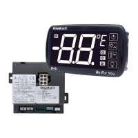
5.12.2 - SIGNAL DUPLICATOR
The X2 remote display device can be connected to the Power Unit
B4U using a special cable that can have a maximum length of 10
meters. The X2 device, powered directly by the B4U, shows the
temperature measured by the Pr1 probe through a 2 ½ digit display.
For more information, see the user manual of the X2 device.
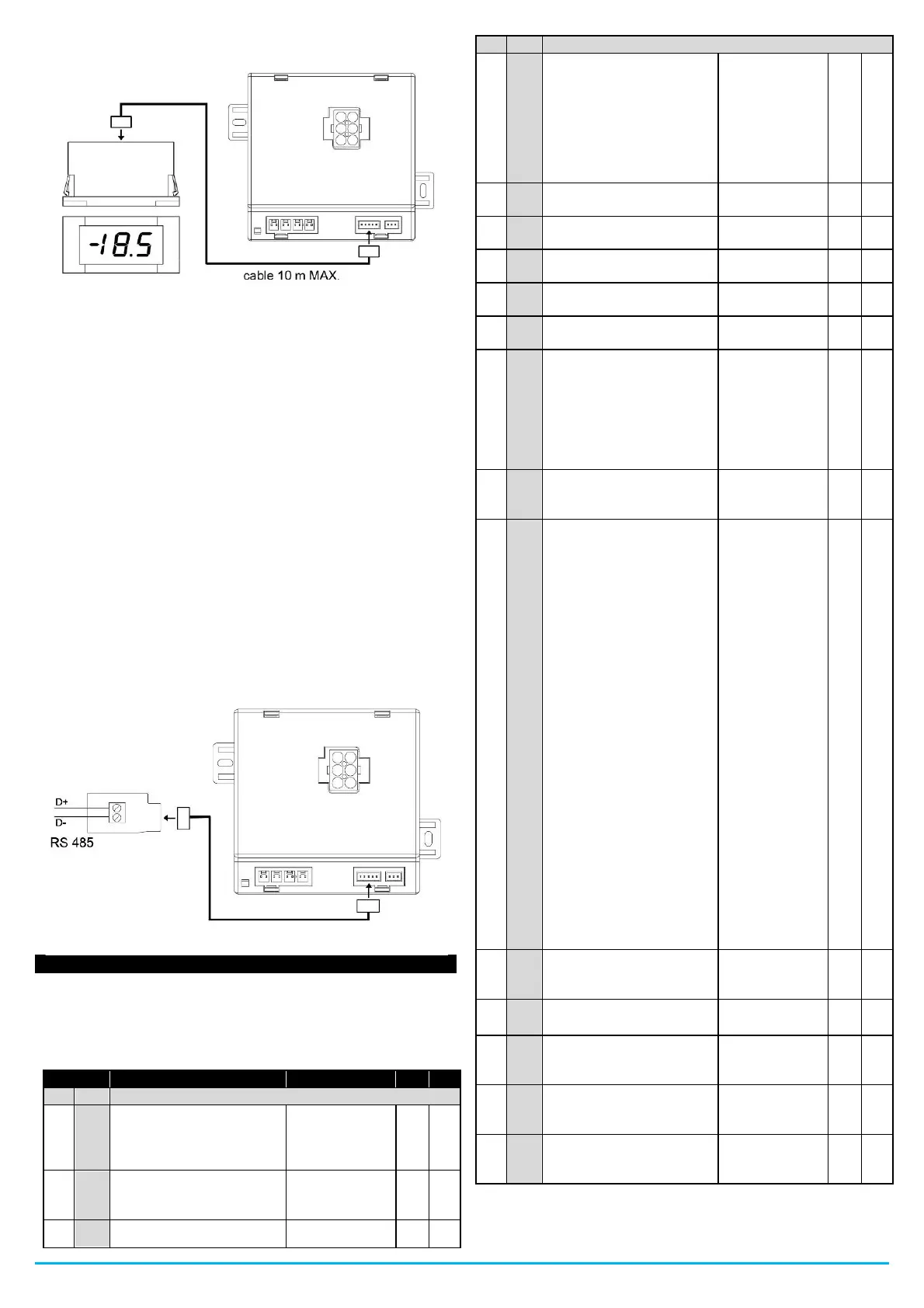
5.12.3 - RS485 COMMUNICATION WITH "KEY TTL"
Through the KEY TTL device (TTL / RS485 interface) and the
appropriate TTL cable, it is possible to connect the B4U to an RS485
serial communication network into which other instruments
(regulators or PLC) are inserted and generally connected to a PC
with a monitoring system.
Through the PC it is possible to acquire all the operating data and
program all the configuration parameters of the B4U.
The software protocol adopted by the B4U is of the MODBUS-RTU
type widely used in many PLCs and supervision programs available
on the market.
If the B4U is used in an RS485 network, program the station address
in the "AS" parameter.
The baud rate (baud rate) of the serial link cannot be configured and
is fixed at 9600 baud.
The KEY TTL converter is powered directly by the Power Unit B4U.
For more information, see the user manual of the KEY TTL device.
Description of all the parameters available on the thermostat.
Some of them may not be present, either because they depend on
the type of thermostat or because they are automatically deactivated
as unnecessary.
Digital input di1 operating
logic:
0 = No function
1 = Door opening
2 = Door opening with fan
lock
3 = Door opening with fan
and compressor lock
4 = External alarm AL
5 = External alarm AL with
control output deactivation
6 = Active Set Point
Selection (SP-SPE)
7 = On / Off
8 = Run “Turbo” mode
9 = Auxiliary output
activation
10 = NOT operational
11 = NOT operational
12 = PrA external alarm with
compressor output
deactivation
13 = HP external alarm with
compressor output
deactivation
14 = LP external alarm with
compressor output
deactivation
 Loading...