Remove all parts from carton, separate by part numbers indicated on parts list, and verify part quantities.
STEP 1 On a soft, non-marring surface, dry t all parts and components to underside of the worksurface as shown above.
STEP 1
A
B
B
C
C
Phillips screwdriver also needed for assembly (not provided)
PART QTY
A. Center Trunk ........................1
B. Column ............................2
C. Side Support ........................2
D. Feet...............................2
E. Handset ............................1
F. Bolt (M6 x 10) .......................8
G. Screw (M5 x 22).....................24
H. Screw (3 x 19) .......................2
I. Bolt 10 x 35) .........................8
J4. Allen Key 4mm ......................1
J5. Allen Key 5mm ......................1
K. Power Cable.........................1
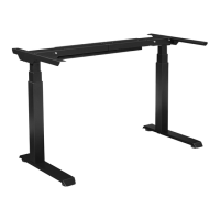
A2EB322 / A2EB222
ASCEND II HEIGHT ADJUSTABLE BASE
ASSEMBLY INSTRUCTIONS
Page 2
 Loading...