max. 16 m
O
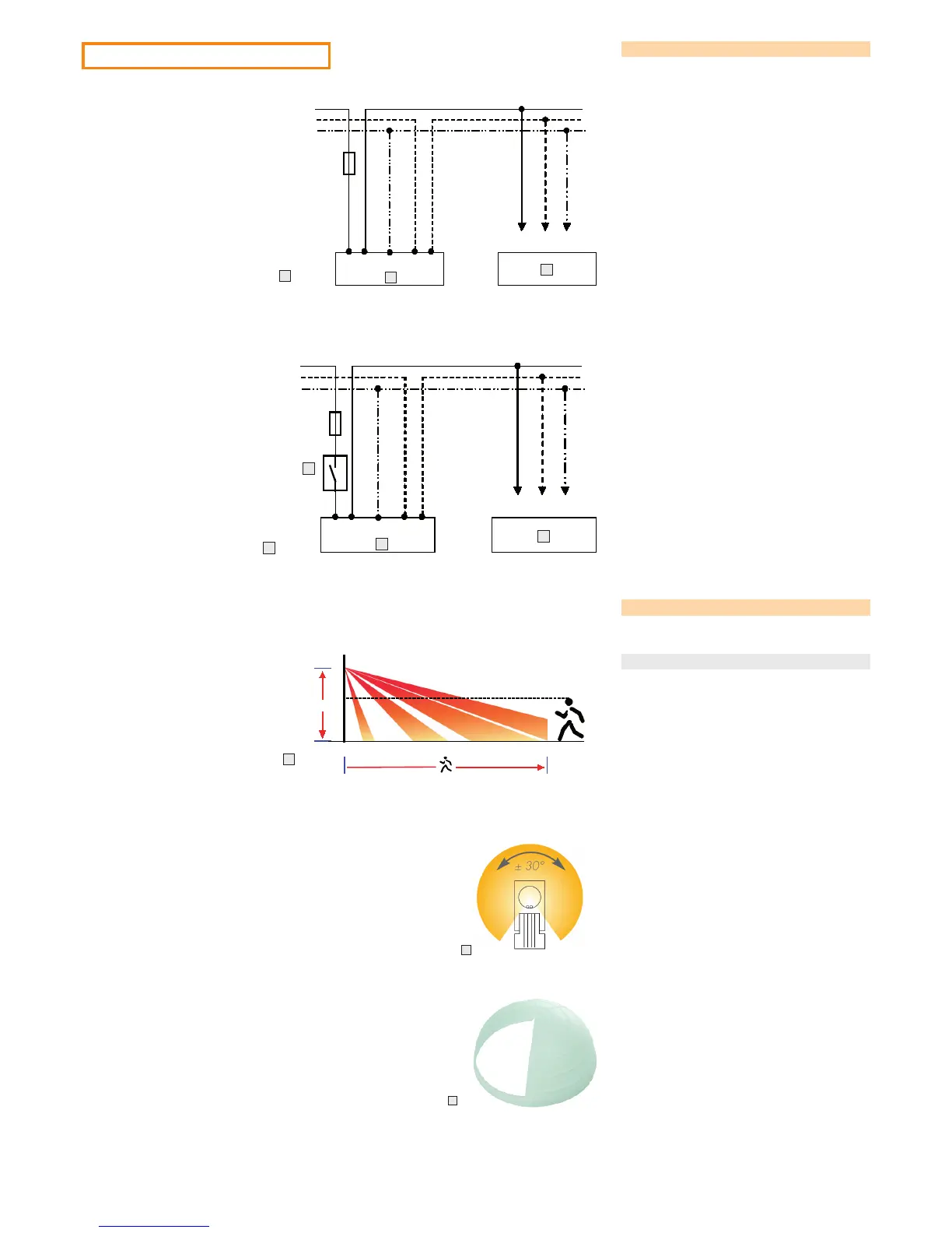
Connection diagram
J Individual circuit
K Load (ECG, lamps, etc.)
L Connection box
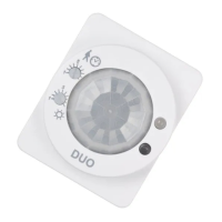
Adjusting the detection area
Motion detection can be checked in test mode; see the operat-
ing instructions.
Horizontal detection area
O Optimal mounting height: 2.5 m
(à Detection area: 16 m)
Permissible mounting height: 2 – 4 m
P Monitoring cone: 290°
Turn the lens to change the orientation (± 30°).
M Individual circuit with optional pushbutton/switch
N Pushbutton/switch
Q The supplied lens cover can be used to limit the detection
area.
CAUTION!
Damage to lens cover!
• Do not cut through the xing ring.
Cut the lens cover separately with a sharp knife if necessary.