INSTALLATION
• The fan must be installed according to the air direc-
tion label on the fan.
• The fan must be connected to duct or equipped with
a safety grille.
• The fan should be installed in a safe way and make
sure that no foreign objects are left behind.
• The fan should be installed in a way that makes ser-
vice and maintenance easy. N.B.! Consider the
weight and size of the fan.
• The fan should be installed in a way that vibrations
not can be transfused to duct or building. To provi-
de this, use for example a flange.
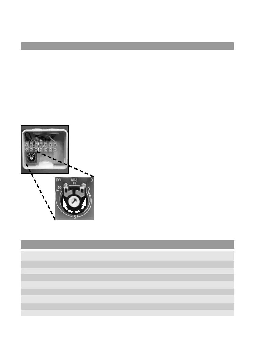
•Regulating the speed can
be done with the built-in
potentiometer, 0-10 V.
An external potentiome-
ter can be connected to
the terminal if necessary.
The internal potentiome-
ter should then be dis-
connected.
• A wiring diagram is applied on the inside of the junc-
tion box or separately enclosed.
• Control that the fan is installed and connected elec-
trically in the right way grounded and with motor
protection.
• Electrical installations must be made by an authori-
zed electrician.
• Electrical installations must be connected to a local-
ly situated tension free switcher or by a lockable
head breaker.
• For single-phase fans a residual current circuit brea-
ker i used (type A).
EMC-COMPATIBLE INSTALLATION
OF EXTERNAL CONTROL LINES
The control cable may not be longer than 60 m. Scree-
ned control cables must be used when the cable length
is longer than 20 m. When using a shielded cable con-
nect the shielding to one side only, i.e. only to the devi-
ce with the protective ground (keep cable short and
with as little inductance as possible!).
Pay attention to suficient distance from powerlines
and motor wires to prevent interferences.
• Attention! Ensure correct polarity!
Never apply line voltage to analog inputs!
17
TECHNICAL DATA
Voltage Current Input Speed Weight Wiring Insulation Motor
V/Hz A W rpm kg diagram class, motor protection
CK 125 C EC 230/50 0,87 105 3390 2,3 4040153 F IP 44
CK 150 B EC 230/50 0,82 99 3400 2,6 4040153 F IP 44
CK 160 B EC 230/50 0,83 103 3390 2,6 4040153 F IP 44
CK 160 C EC 230/50 1,06 132 3170 3,7 4040143 F IP 44
CK 200 B EC 230/50 1,21 154 3250 3,7 4040143 F IP 44
CK 250 B EC 230/50 1,25 155 3330 3,9 4040143 F IP 44
CK 315 B EC 230/50 1,26 157 3030 4,5 4040143 F IP 44
CK 315 C EC 230/50 1,00 226 2620 4,8 4040143 F IP 44
 Loading...