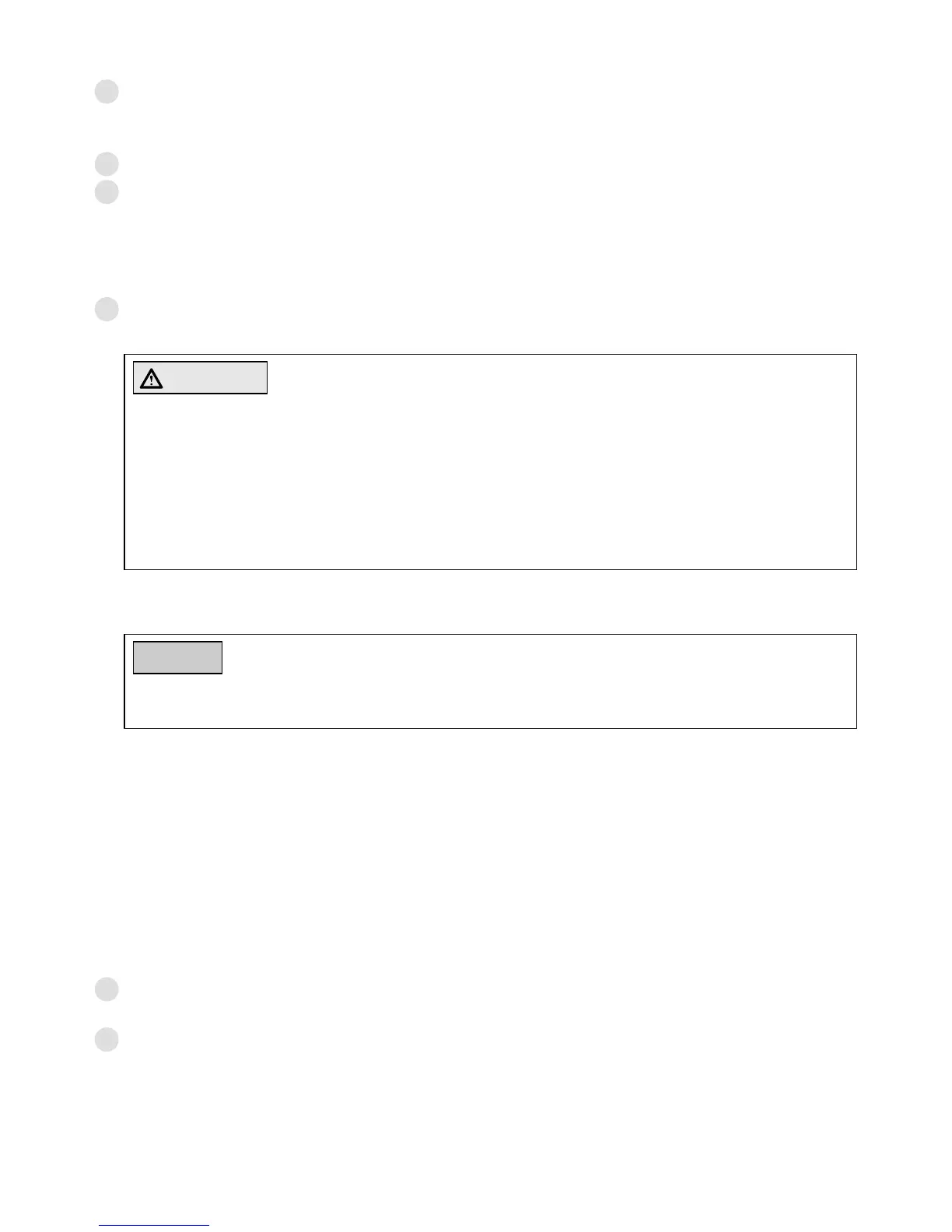
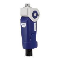
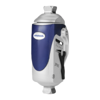
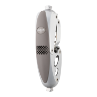
Ottobock | 233R93
4.1.1 Bench alignment with alignment tool (Fig. 8)
1
Position the middle of the foot (MF) approx. 30 mm anterior to the alignment reference line.
This applies to all foot components that are recommended for use with 3R93, independently
2
Add 5 mm to the required heel height. Set correct outward rotation of the foot.
3
Clamp the knee joint using the appropriate adapter insert. Place the alignment reference
point (= knee axis) 10 mm posterior to the alignment reference line. Take into account the
knee-ground distance and outward rotation of the knee (the adapter insert in the alignment
tool provides for a rotation of approx. 5°). Recommended sagittal positioning of the alignment
reference point: 20 mm above the medial tibial plateau.
4
Connect the prosthetic foot to the modular knee joint using the enclosed 2R77 Tube Adapter
(see Fig. 1, item 1).
CAUTION
Risk of falling due to incorrectly mounted tube adapter. Incorrect mounting of the tube
adapter in the tube clamp (e.g. when using the insertion depth for length adjustment) can
result cause the patient to fall.
lead to a risk of falling.
Observe the following instructions.
a. Do not clamp the tube into a vice! Cut the tube using 719R2 Tube Cutter placed at a right
angle to the tube.
NOTICE
Risk of damage to the prosthesis: For reasons of structural strength, the residual pieces
of cut tube adapters must not be used as components in prostheses.
b.
Afterwards carefully deburr the inside and outside of the tube using the 718R1 Tube De-
burring Knife.
c. Do not make any length adjustment by varying the insertion depth. Insert the tube into the
knee joints‘ tube clamp all the way to the stop.
d. Tighten the cap screw of the tube clamp using the 710D1 Torque Wrench. Torque: 10 Nm
(Fig. 2, item D).
e. Connect the tube adapter to the foot. To do so, tighten the 506G3 Set Screws which are
located next to each other at the distal end of the tube adapter using the 710D4 Torque
Wrench. Torque: 10 Nm. (For completion of the prosthesis, apply 636K13 Loctite® to the
set screws and tighten all set screws with 15 Nm).
5
Mark the centre of the socket proximally and distally on the lateral side. Draw a line through
both marks from socket brim to the distal end of the socket.
6
Now position the socket such that the alignment reference line passes through the proximal
-


 To Next Page