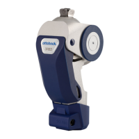
28 | Ottobock 3R93
Problem Cause Action
Relevant especially for patients with
a high body weight: Braking effect
is too aggressive; initiation of the
Brake sensitivity is set
too high.
Reduce brake sensitivity: Turn
adjustment screw clockwise.
Relevant especially for patients with
a low body weight: Braking effect
unstable in the stance phase.
Brake sensitivity is set
too low.
Increase brake sensitivity: Turn ad
-
justment screw counter-clockwise.
(Delivery condition = level 4 = high-
est brake sensitivity. Do not turn
the screw counter-clockwise any
further!)
4.2.4 Adjusting the brake tolerance
CAUTION
Risk of falling after adjusting the brake tolerance. Adjusting the brake tolerance can cause
the brake to get blocked or stuck and, as a result, cause the patient to fall.
Observe the following instructions.
Upon delivery the brake tolerance is optimally adjusted.
In spite of correct alignment of the prosthesis (see Section 4.1) and correct brake setting it may
become necessary to modify the brake tolerance (see table below).
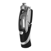
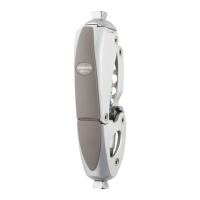
To adjust, slightly turn the tension compensation screw clockwise or counter-clockwise (Fig. 6,
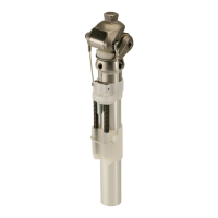
item B) using 710H10=2X3 Adjustment Wrench (Fig. 1, item 2).
Problem Cause Action
Flexion and extension movements
are impeded when the prosthesis is
unloaded (noticeable resistance to
movement); the brake gets stuck.
Brake tolerance upon
load bearing is too low.
Increase brake tolerance: Care-
fully turn the tension compensation
screw clockwise.
extension movements upon load
bearing
After longer use, the
brake tolerance upon
load bearing is too high.
Reduce brake tolerance: Carefully
turn the tension compensation
screw counter-clockwise.
Optimum setting (as delivered) is achieved, when there is no noticeable brake play upon load bear-
ing and the pendulum movement of the prosthetic lower leg is not impeded during the swing phase.
4.2.5 Adjusting the swing phase control
The mechanical swing phase control of the 3R93 can be set to 6 levels by changing the tension
of the integrated spring extension assist using 710H10=2X3 Adjustment Wrench (Fig. 1, item 2).
Upon delivery the spring adjustment ring (Fig. 7, item A) is set to level 1.
If necessary, the spring effect can be adjusted as follows:
 Loading...