6
HUB 10 and HUB 4 Parts
Each HUB comes with su cient fasteners, cables and bushings for most common installations. Please
see the enclosed hardware kit for speci c parts.
Accessories
OBCATV-3 Three-foot CAT5e cable with green jacket
OBCATV-6 Six-foot CAT5e cable with green jacket
OBCATV-10 Ten-foot CAT5e cable with green jacket
OBCATV-50 Fifty-foot CAT5e cable with green jacket
Mounting
The OutBack HUB can be wall-mounted in any orientation. Both the FLEXware 500 and 1000 systems
as well as previous OutBack enclosures have mounting holes for convenient HUB installation.
To mount a HUB to either a FLEXware 500 or 1000:
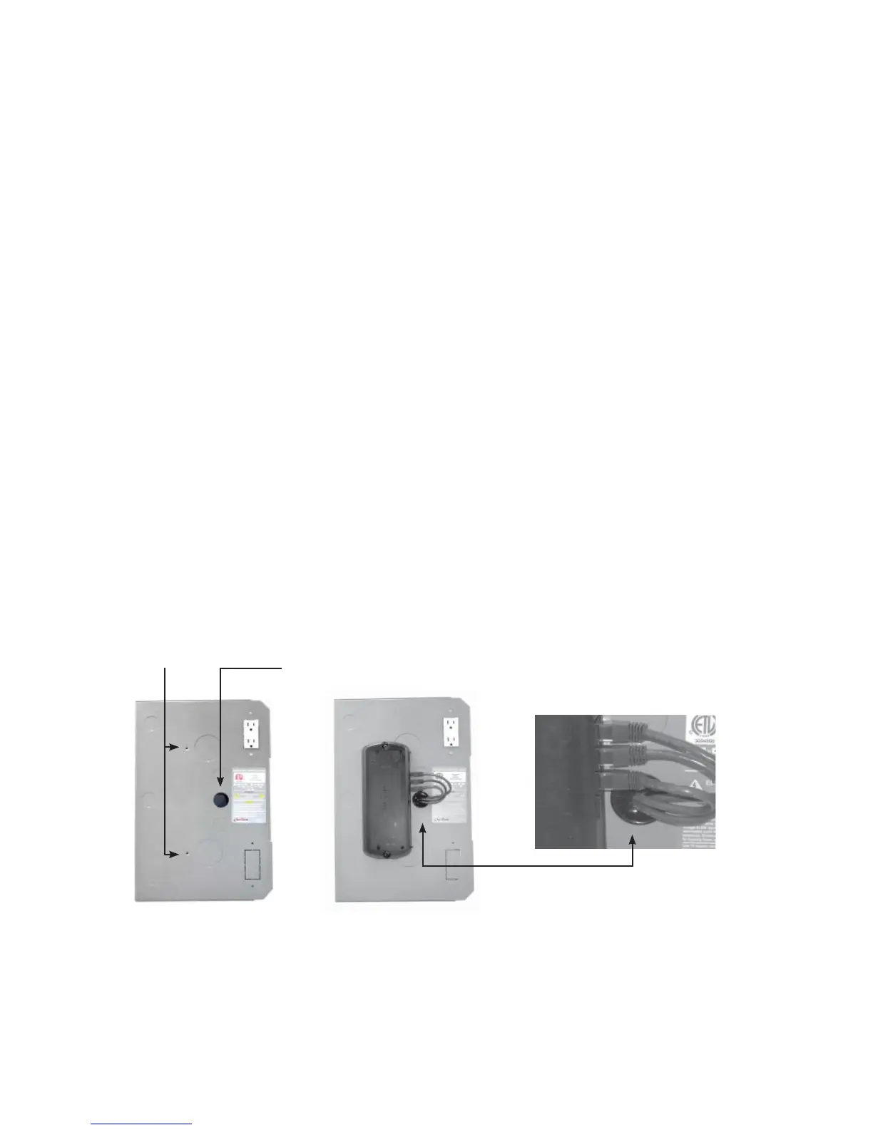
• Remove the knockout(s) from the side of the 500 or 1000
• Insert the snap-in bushing(s) supplied with the HUB.
• Secure the HUB using the supplied #10 sheet metal screws.
• Pull the CAT5e cable(s) through the knockout(s) and attach to the HUB Port(s).
To mount to a wall or other secure non-enclosure surface:
Either HUB model can be attached using two 1 5/8” drywall screws or their equivalent.
FLEXware 500 AC Enclosure HUB 4 attached to enclosure
Conduit knockout
removed
Openings for #10 X 1/2”
Phillips screws (included
with each HUB)
CAT5e cables are protected by
bushing inserted into conduit
knockout
 Loading...