Page 19Page 18
900-0125-12-02 Rev A
©2017 OutBack Power Technologies. All Rights Reserved.
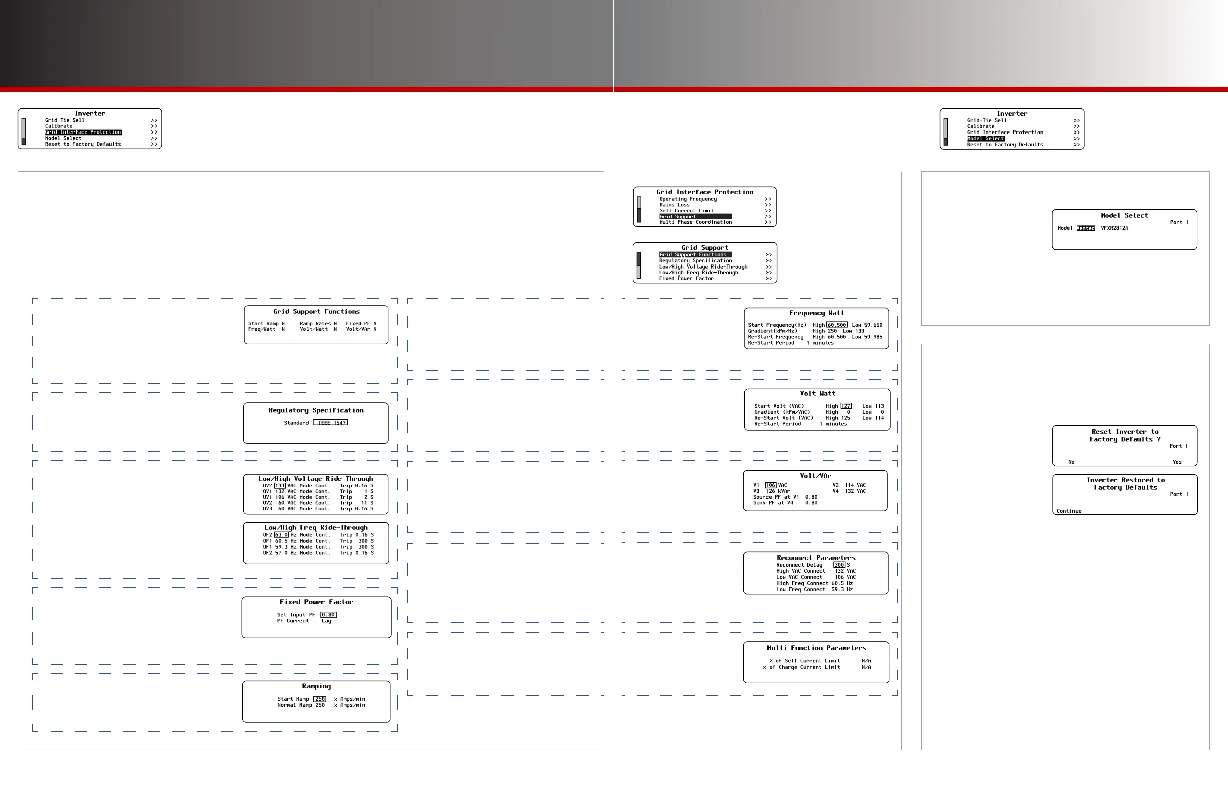
I-15. Model Select
In the FXR class, this
designates whether
an inverter is a vented
or sealed model.
If replacing the control PCBA in a sealed model, it must
be set for that model. The default setting is Vented.
In the Radian class, this adjusts current settings based
on the model and size.
Inverter Settings
Grid Support
I-16. Reset to Factory Defaults
This screen allows the user to erase the settings from
the selected inverter and start over with the values
programmed at the factory.
Entering this screen brings up the query Reset
Inverter to Factory Defaults?
Use the soft keys to select No or Yes.
● If <No> is selected, the screen returns to the Inverter menu.
No changes will be made to any settings.
● If <Yes> is selected, the inverter’s settings immediately
change to the original factory values. The screen displays
the message Inverter Restored to Factory Defaults. A
<Continue> soft key will appear. Pressing this key returns
the screen to the Inverter menu.
NOTE: Some items retain the present setting even
when the inverter is reset. These settings include
Output Voltage, all items in the Calibrate menu,
Model Select, and all items in the Grid Interface
Protection menu (including Grid Support). The
inverter Operator’s Manual species these settings.
I-14. (Grid Interface Protection, continued)
Grid Support
This set of menus contains the individual values required by specic regions or utility companies. All items
shown here are pre-programmed to the requisite values when a .GIP le is implemented.
The Grid Support function is automatically activated when the GridZero or Grid Tied input modes are selected.
(See page 11.) All items described on this page are enabled according to regulatory specications.
◘ Grid Support Functions — indicates
whether the listed functions are
operational. See the following items.
Start Ramp
Frequency-Watt
◘ Regulatory Specification — after
uploading the .GIP files, this indicates
the code or utility company regulation
that the preloaded settings follow.
◘ Low/High Voltage and Frequency
Ride-Through — the high and low trip
(disconnect) levels and times for AC
voltage and frequency disturbances.
OV (Over-voltage) levels 1 and 2
UV (Under-voltage) levels 1, 2, and 3
OF (Over-frequency) levels 1 and 2
UF (Under-frequency) levels 1 and 2
Ramp Rates
Volt-Watt
Fixed PF
Volt/VAr
◘ Fixed Power Factor — the power factor
to be produced by the inverter when
selling or other forms of offsetting.
Set Input PF
PF Current
◘ Ramping — the rate of power increase
when first ramping (Start Ramp) and
subsequent increases in selling or other
forms of offsetting (Normal Ramp).
◘ Frequency-Watt — responds to
changes in AC input frequency by
altering offsetting or charging.
◘ Volt-Watt — responds to changes in
AC input voltage by altering offsetting
or charging.
Start Frequency
F/W Gradient
Re-Start Frequency
Re-Start Period
Start Volt
Gradient
Re-Start Volt
Re-Start Period
◘ Volt/VAr — responds to changes in
AC input voltage by supplying or
consuming reactive power to affect the
power factor.
V (input voltage
level) 1 through 4
Source PF at V1
Sink PF at V4
◘ Reconnect Parameters — the AC
voltage, frequency, and time limits which
must be met before the inverter can
connect (or reconnect) to the utility grid.
Reconnect Delay
High VAC Connect
Low VAC Connect
High Freq Connect
Low Freq Connect
◘ Multi-Function Parameters — not in
use at this time. These items are for use
in future revisions of firmware.