EasyManua.ls Logo

Outback FLEXmax 80 User Manual

Outback FLEXmax 80
2 pages
To Next Page IconTo Next Page
Page #1 background imageLoading...
Page #1 background image
900-0134-01-00 Rev D.vsd\QSG\2014-07-21
©2012 OutBack Power Technologies. All Rights Reserved.
In 23.2 V 0.0 A
Out 27.6 V 0.0 A
0.000 kW 0.0 kWH
AUX: OFF Sleeping
Charger Aux Light
EQ Misc Advanced
Logging Stats
EXIT
GO
LCD Screen
Main Menu
Soft Key
Buttons
Soft Key
Commands
<EXIT>,
<GO> etc.
Navigation:
1
2
Advances to the
End-of-Day Screens
Advances to the
Main Menu Screens
IN 23.2 V 0.0 A
OUT 27.6 V 0.0 A
0.000 kW 0.0 kWH
AUX: OFF Sleeping
Status Screen
OutBack 24V
Power
Systems
Charge Controller
Startup Screen
NOTE: See the FLEXmax Series Owner’s Manual for details on
the settings available in the main menu.
PV Input Voltage
Battery Voltage
AUX Status
Instantaneous Kilowatts
PV Input Current
Output Current
Mode of Operation
Daily Accumulated
Kilowatt-hours
Select this option to proceed
Available menus
Adjusts the set points value
Switches between devices on the
ports of the Communications HUB
Soft Key Color Code:
Navigation colors
Selects a function (e.g., ON, OFF, AUTO)
NOTE: Soft key functions will vary depending on the selected
menu and are defined by the word above the key in the LCD.
If accompanied by a dashed
line, pressing that soft key will
return the user to the location
identified by the dashed line.
This will vary depending on the
devices in the system.
Indicates a 1-screen movement within a
menu. These are color-coded according to
their function or purpose.
Models:
FLEXmax 80: 80 amps maximum continuous
output current (up to 40°C without thermal derating)
FLEXmax 60: 60 amps maximum continuous
output current (up to 40°C without thermal derating)
Features:
Maximum Power Point Tracking
Supports 12, 24, 36, 48, and 60 Vdc
battery voltages
Backlit display screen (LCD) with 80 characters
(4 lines, 20 characters per line)
Last 128 days of operational data logging
Voltage step-down capability allowing a higher PV
array voltage configuration
Manual and automatic equalize cycles
Screen Versions:
English
Spanish
Australian (English with different default settings)
FLEXmax Charge
Controller
PV
+
PV
BAT
BAT
+
MATE
Port
(RJ45)
RTS
Port
(RJ11)
Torque =
4 Nm (35 in-lb)
1 2
Terminals
LCD Screen
Soft Keys
IMPORTANT: Example only. Actual wiring may vary.
All configurations must comply with local and national
electric codes. Consult your local electric authority to
ensure compliance.
(RTS)
PV Combiner Box
Photovoltaic Array
(PV)
Negative
Positive
Ground
DC LEGEND
Battery Bank
Vented Battery Enclosure
DC Disconnect
Ground Bus
ON
OFF
System Display
and Controller
(MATE3)
Maximum PV Input Wattage
per Charge Controller
Battery
Bank
Voltage
Maximum PV
Input Wattage
for the
FLEXmax 80
Maximum PV
Input Wattage
for the
FLEXmax 60
12 Vdc 1000 W 750 W
24 Vdc 2000 W 1500 W
36 Vdc 3000 W 2250 W
48 Vdc 4000 W 3000 W
60 Vdc 5000 W 3750 W
Question and Answer IconNeed help?

Do you have a question about the Outback FLEXmax 80 and is the answer not in the manual?

Outback FLEXmax 80 Specifications

General IconGeneral
Maximum Current80 A
Nominal Battery Voltages12, 24, 36, 48, 60V
Maximum PV Open Circuit Voltage150 VDC
Efficiency98%
Operating Temperature Range-40°C to +60°C
Maximum Input Power4000W
Auxiliary Output12 VDC
CommunicationRS-232
ProtectionOvercurrent, Overtemperature

Summary

FLEXmax Charge Controller Quick Start

Product Models and Features

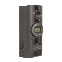
Details the FLEXmax 80/60 models and their key capabilities like MPPT and battery voltage support.

System Components and Wiring Diagram

Illustrates the typical solar system layout, connections, and key components like PV array and battery bank.

Controller Interface and Navigation

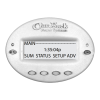
Explains the startup screen, status display, navigation methods, and soft key functions on the charge controller.

Configuration and Menu Navigation

System Settings Adjustment

Guides on how to change the language, screen version, and system voltage settings of the controller.

Main Menu Access and Options

Details how to access the main menu and lists key configuration sections like Charger Setup and Battery Equalize.

Charger Setup

Adjusts charge voltage set points for current limit, absorbing, and float charging.

Aux Output Control

Manages the secondary control circuit for functions like vent fans, AGS, or alarms.

Battery Equalize

Activates manual or automatic battery equalization cycles to maintain battery health.

Data Logging and Statistics

Accesses recorded power production information and peak system statistics like KWH and Ah.

End-of-Day Summary Screens

Explains how to view historical daily operational data, including voltage, current, and energy production.

Related product manuals