Page 2
900-0093-01-00 Rev C
©2020 OutBack Power. All Rights Reserved.
Specifi cations
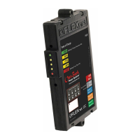
0.7" (1.9 cm)
3.7" (9.4 cm)
6.6"
(16.8 cm)
Features
A: State of Charge Indicator Lights
B: Mounting Screws
C: Hub Cable Port
D: Wiring Block
Specifications
Battery Voltage Input Range................. 8 to 80 Vdc
Battery Voltage Resolution ................... 0.1 Vdc
Number of Current Channels................ 1 to 3 (source or load)
Current Range (Each Channel) ............ +/- 1000.0 amps DC
Current Resolution................................ 0.1 amps DC
State of Charge Display........................ 0 to 100% (1% increments)
Aux Relay Confi guration ....................... SPST magnetic latching relay
Aux Relay Max Rating .......................... 5 amps @ 30 Vdc
Current Shunt Type (not incl.) ............... 500A / 50 mV
Display .................................................. MATE3s (not included) / LED indicators on unit
Battery Amp Hour Capacity Range ...... 100 to 10,000 AH
Data Logging Memory .......................... Most recent 128 days
Programmable Aඝච Relay Settings ...... 8 to 80VDC / 0 to 100% SOC / 0 to 240 minutes
Accuracy ............................................... 0.5% of reading
Operating Temperature Range ............. 0 to 50°C / 32 to 122°F
Mounting ............................................... ¾" panel mount breaker slot or surface mount using built-in mounting bars
Warranty ............................................... Standard 5 year
Weight .................................................. 5 oz (0.14 kg)
Dimensions ........................................... 0.7 × 3.7 × 6.6ʺ (1.9 × 9.4 × 6.8 cm)
C
D
B
A
B
Page 19
FN-DC Field Calibration
This section outlines the procedure for calibrating a FLEXnet DC Battery Monitor that has already
been installed in a system.
Required Equipment
○ Digital Multi-Meter (DMM)
○ Jeweler screwdriver
○ Previously existing system (MATE3s, HUB, inverter, and/or charge controller)
To Calibrate:
1. Ensure battery bank is fully charged.
2. De-energize system.
3. Remove FN-DC from its mounting location. Maintain all wired connections, including green
communications cable to HUB.
4. Remove FN-DC front cover.
○ Ensure informational sticker is facing up and terminal block is at the far end.
Using the two push tabs, remove the front cover.
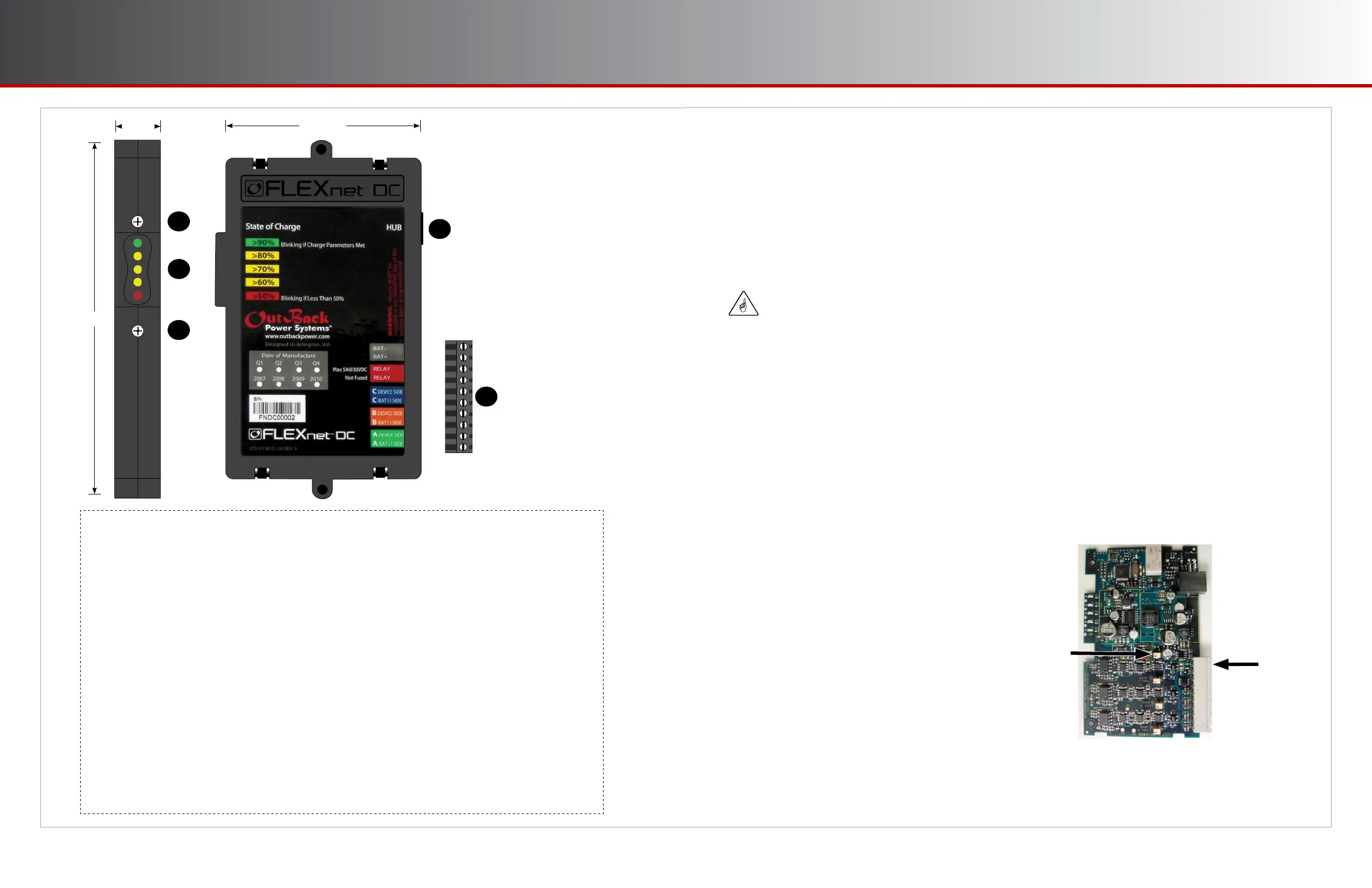
5. Remove red sealant from the R83 trim pot (potentiometer). See fi gure below.
6. Energize system.
7. Measure battery voltage with DMM at terminals 1 and 2
on FN-DC inputs.
8. Read battery voltage from the MATE3s FLEXnet DC
screen. (See page 8.)
9. With a jeweler's screwdriver, adjust the R83 trim pot
until the displayed voltage from the FLEXnet DC screen
matches battery voltage measured with the DMM.
10. Replace front cover.
11. Replace FN-DC in system.
IMPORTANT:
Take all necessary safety precautions when working on energized equipment.
R83
Terminals
1 and 2
 Loading...