2/99 2-1 U3-1021
Westinghouse Proprietary Class 2C
Section 2. Link Controller Hardware
2-1. Section Overview
This section describes the Ovation Link Controller module, the wiring, the optional
jumpers, and the diagnostic LEDs used to provide communication between an
Ovation Controller and a third-party device or system. This communication is done
via a serial RS-232, RS-422, or RS-485 data link.
Prior to initializing and using the Link Controller module, verify that the hardware
has been properly configured.
2-2. Module Description
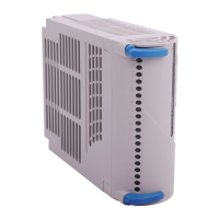
This section describes the Ovation Link Controller module which consists of three
parts (refer to
Figure 2-1):
• Base Unit (containing the field terminations)
• Electronics Module
• Personality Module
2-2.1. Base Unit
The base unit (containing two terminal blocks) mounts onto a DIN rail. Each
base unit accommodates two I/O modules. If you use only one I/O module, you
still must use a base unit that contains two terminal blocks.
The footprint of the base unit (containing Electronic and Personality module) is:
27.9 cm Long (11 in)
12.7 cm Wide (5 in)
16.5 cm High (6.5 in)
2-2.2. Electronics Module
The Electronics module (configured by adding the appropriate Personality
module) fits into the base unit. There is one Electronics module group for the
Link Controller Module:
• 1C31166G01 provides for communication to a third-party device or system.

 Loading...