2017 1
Thermostatic radiator valves
Thermostats “Uni LH” and “Uni LD”
Content:
Page 1 General information
Installation of the valve
Installation of the thermostat
Figures and symbols on the thermostat
Page 2 Limitation of the control range
Page 3 Locking of a setting
Recalibration
Cancellation of the limitation of locking
Page 4 Replacement of the gland nut
Checklist for troubleshooting
General information
Thermostatic radiator valves control the room temperature by
modifying the ow of hot water through the radiator. As the heat
demand is often very low (especially during transition periods), the
valves are opened by the thermostat to only a small amount. As
a result, ow noises may occur due to high differential pressures.
To prevent these noises, differential pressure independent
thermostatic valves, such as “AQ”, or devices inuencing the
differential pressure should be used; for example adjustable
circulation pumps, automatically working differential pressure
regulators or differential pressure relief valves.
It is recommended to adjust the ow temperature to the
outside temperature, preferably by using a weather guided ow
temperature control.
Further information can be obtained from the manual “User
instructions” and the technical data sheets “Thermostats”
and “Thermostatic radiator valves”.
Installation of the valve
The radiator valve is to be installed so that the thermostat is in a
horizontal position and a good circulation of air is guaranteed. If
this is not possible, a thermostat with remote sensor or remote
control should be used. It is most important that the capillaries
are not kinked or attened.
The radiator valve is installed in the supply pipe to the radiator,
with the ow in the direction of the arrow.
When using compression ttings, the thread of the tting and
the compression ring are slightly oiled at works. Do not use any
additional lubricant! Do not allow the oil or lubricant to come into
contact with the EPDM valve disc. EPDM is not oil resistant.
When using compression ttings for thermostatic valves with
female threaded connection (only possible for sizes DN 10,
DN15 and DN 20), the “Ox” compression ttings are to be used
to guarantee a perfect sealing function between the pipework
and the thermostatic valve.
It is important that the pipes are cut to the correct length at a right
angle to the centre line. The ends of the pipe must be free from
burrs and undamaged.
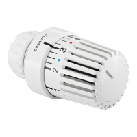
Tactile setting device
Indicator mark
Minor graduation
Direction “warmer”
Basic setting “3”, about 20 °C
Direction “colder”
Graduation gure
Tactile setting device
Handgrip
Memo disk
Collar nut “Uni LH”
or squeeze connection “Uni LD”
(0 = Complete shut off
This symbol can only be found on thermostats with ‘0’
setting)
= Frost protection symbol,
in this position the valve opens automatically when
the room temperature drops below 7 °C.
1 = about 12 °C
2 = about 16 °C
3 = about 20 °C
4 = about 24 °C
5 = about 28 °C
Installation instructions for the specialised installer
Figures and symbols on the thermostat
When using thin walled and very soft pipes, reinforcing sleeves
have to be used. The reinforcing sleeve supports the pipe and
provides the strength to enable the necessary compression.
Reinforcing sleeves cannot be used for pipes with welded
seams. The recommendations of the pipe manufacturers have
to be observed in any case. If necessary, a practical test has to
be carried out.
The special screwed ttings “Cot S” or press ttings “Cot
P/PD/PDK” may be used for the Oventrop composition pipe
“Copipe”. The installation instructions supplied with the ttings
must be observed.
When choosing the operating uid, the latest technical status
has to be considered (e.g. VDI 2035 - Avoidance of damage to
hot water heating systems).
All radiators and pipework must be ushed thoroughly to
prevent any problems caused by welding beads and dirt.
When converting old heating systems, it is recommended that
a plastic strainer should be tted at the inlet port of all radiator
valves.
Do not t the thermostat until all building work has been
completed. During the construction period, the valve can be
operated with the protection cap. The cap is not to be used for
permanent shut-off of the valve against system pressure (e.g.
while the radiator is removed). In this case protect the valve
outlet with a metal cap.
Installation of the thermostat
To ensure an easy installation, the handgrip must be opened to
the maximum position (gure “5”). In this position, the collar nut
(“Uni LH”) or the squeeze connection (“Uni LD”) of the thermostat
may be easily tted to the valve body.
Turn the thermostat so that the indicator mark is facing up. Hold
in this position and tighten the collar nut without using excessive
force.
Pipe shape after
tightening
Reinforcing sleeve
Compression nut
Compression
ring
Compression tting before
tightening. Remove pipe
insulation far enough.
The minor graduations
between the gures 2 – 4
represent a change of the
room temperature of about
1 °C.
}