Cancellation of the limitation or locking
If the control range is limited or locked with the clips, the handgrip
cannot be removed as shown in illustration 1 or 12. In this case,
please proceed as follows:
Illustration 16 : Locked setting:
Insert the tool (item no. 1989100)
into the handgrip so that one
bridge is in the groove before
and one bridge in the groove
after the indicator mark. Push
the tool in the direction of
the arrow to loosen the clips.
Remove the tool.
Limited control range: Turn the
handgrip to the upper or lower
nominal value of the control
range.
2017 3
16
Locking of a setting
To avoid unauthorised tampering, any temperature setting
of the thermostat can be locked. Example: Locking of the
temperature setting to gure “2”. (Equals about 16 °C, e.g.
for hallways and bedrooms). To do so, remove the handgrip
as shown in illustration 1. Then turn the sensor casing until
the calibration mark (bore or white stroke) is in line with the
indicator mark as shown in illustration 2.
Illustration 8: Ret the
handgrip loosely so that
gure “3” is in line with the
indicator mark.
8
Illustration 9: Turn the handgrip
to gure “2” while pressing it
gently. Remove the handgrip.
(The calibration mark on the
sensor casing is now turned to
the right
.)
9
Illustration 10: The two clips
on the inner side of the
handgrip are to be removed
as shown in illustration 3 and
are tted into the grooves
before and after gure “2”.
(The groove right in front of
gure “2” thus remains free.)
10
Illustration 11: Ret the
handgrip so that gure “2” is
in line with the indicator mark.
The setting is now locked to
gure “2” (about 16 °C). Push
down the handgrip with the
hand until it engages.
11
Recalibration:
The thermostat is adjusted at works to 20 °C = gure “3”.
In case of misalignment, recalibration can be carried out as
follows:
12
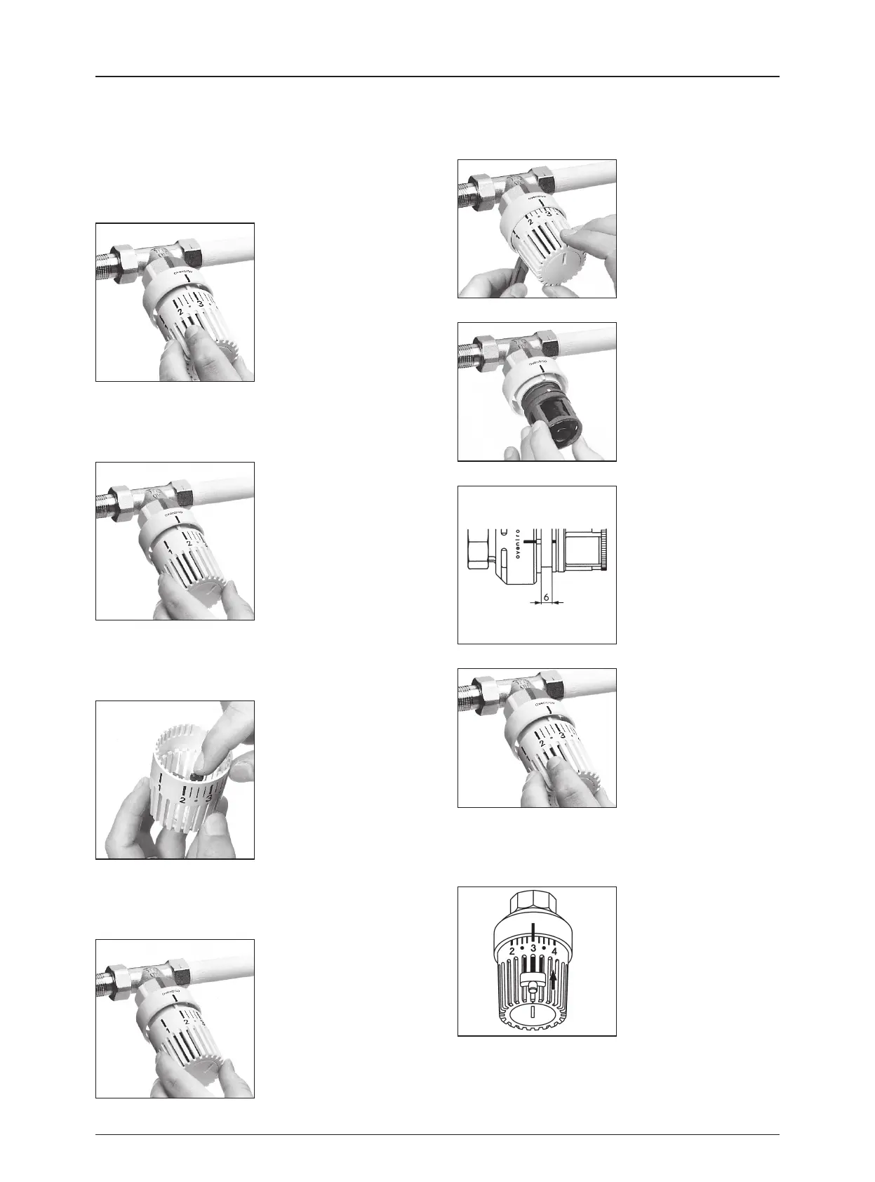
Illustration 12: Remove the
handgrip with the tool (item
no. 1989100) or with a pin, e.g.
with the push button of a pen.
Insert the tool/pin in the hole
provided on the lower side of
the thermostat. By turning the
handgrip to the right to the
shut-off position, it is easily
removed.
13
Illustration 13: Remove the
handgrip. Turn the sensor
casing to the right until it is fully
screwed into the body of the
thermostat, then turn it to the
left again until the calibration
mark (bore or white stroke) is
in line with the indicator mark.
14
Illustration 14: If the sensor
casing is for some reason
unscrewed completely from
the body of the thermostat,
please make sure that because
of the double thread, the
correct start thread is used
when refitting the sensor
casing. After recalibration, the
distance between the body and
the sensor casing has to be
about 6 mm.
15
Illustration 15: Refit the
handgrip so that gure “3” is
in line with the indicator mark.
Push down the handgrip with
the hand until it engages.
Thermostatic radiator valves
Thermostats “Uni LH” and “Uni LD”
Insert the tool into the handgrip so that one bridge is in the groove
before and one bridge in the groove after the indicator mark. Push the
tool in the direction of the arrow to loosen the clips. Remove the tool.
The handgrip can now be removed as shown in illustration 1.
Remove the clips and reposition.
 Loading...