EasyManua.ls Logo

Overstayer 8755DS - User Manual

Overstayer 8755DS
11 pages
Print Icon
To Next Page IconTo Next Page
Loading...
MODULAR CHANNEL
STEREO MODEL 8755DS
MODULAR CHANNEL
STEREO MODEL 8755DM
REFERENCE
v2.1
Question and Answer IconNeed help?

Do you have a question about the Overstayer 8755DS and is the answer not in the manual?

Summary

Safety and Installation

Installation Procedures

Steps for safely connecting and setting up the equipment, including power and ventilation.

Safety Warnings and Precautions

Critical warnings regarding electrical shock, fire hazards, and environmental conditions for safe operation.

Signal Flow and Features

Signal Flow Explanation

Detailed explanation of the audio signal path through filters, EQ, compression, and harmonics.

Modular Channel Features

Overview of key features including stereo path, filters, EQ, VCA compressor, and harmonics stages.

Front Panel Controls

Input Section Controls

Controls for input gain, polarity, and signal source selection including MIC, LINE, and INSTRUMENT.

Bandwidth and Filter Controls

Controls for high-pass and low-pass filters, resonance, and distortion shaping (CURVE).

Equalizer Section

Equalizer Controls

Description of EQ switches and controls for bass, presence, and treble frequencies.

Master Bypass

Information on the ENGAGE switch for master bypass and its behavior with different input signals.

Compressor and Amplitude Control

Compressor Controls

Detailed explanation of BEHAVIOR, THRESHOLD, ATTACK, RELEASE, and MAKEUP controls.

Sidechain and Output Controls

Controls for sidechain filtering, SC POST/PRE selection, and output ceiling.

Harmonics, Saturation, and Feed Mixer

Harmonics and Saturation Stages

Using DRIVE, MAS, SAT, and HEX switches to add harmonics and saturation to the signal.

Feed Mixer Controls

Managing signal levels for DRY/EQ, COMP, and SAT feeds with mute switches.

Rear Panel Connections

Audio and Power Connections

Description of all rear panel connectors for audio I/O, insert points, and DC power.

Contact and Support Information

Information on how to contact Overstayer for questions and support.

Overview

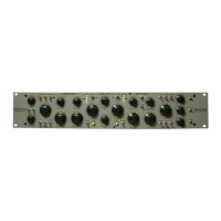
The Overstayer Modular Channel 8755DS/8755DM is a stereo channel strip designed for audio processing, featuring filters, EQ, compression, and harmonics stages with sophisticated routing and a series/parallel mixer matrix. It utilizes high-quality components and circuitry, aiming to provide console-like fidelity for full mixes while also offering extreme processing capabilities.

Function Description:

The device is an analog channel strip that offers comprehensive audio processing. It includes:

  • Input Section: Balanced line inputs and outputs, high impedance unbalanced instrument inputs, and microphone inputs (DM version).
  • Filters: Wide-ranging high and low pass filters with resonance capable of full oscillation.
  • Equalizer (EQ): Features high and low shelves with three selectable frequencies each, and a fully sweepable proportional Q mid-range band.
  • Compressor: A VCA compressor with peak and RMS detectors, three-position attack and release controls, a BEHAVIOR control for unique envelope shaping, a sidechain high pass filter, and an external sidechain input.
  • Harmonics/Saturation: Independent harmonics stages that can be engaged in any combination, with a DRIVE control to adjust the amount of harmonics and saturation. Stages include MAS circuitry (2nd or 3rd harmonic), a rich saturation stage (SAT), and a deep distortion stage (HEX).
  • Feed Mixer: A mixer matrix with faders and mute switches for DRY/EQ, COMPRESSOR, and full wet path SATURATED signals, allowing for series and parallel routing and composited mixing.

Important Technical Specifications:

  • Signal Path: Stereo.
  • Input/Output: Balanced line inputs and outputs, high impedance unbalanced instrument inputs. Microphone inputs are transformer-coupled (8755DM only).
  • Gain Matching: Trimmed for better than 1dB matching through a wide range of settings, though deviations are possible, especially with high filter resonance.
  • Headroom: The fixed output ceiling correlates to specific OUTPUT control positions for converters calibrated to -18dBFS: '6' for 7dB headroom, '7' for 4dB headroom, '8' for 0.1dB headroom.
  • Power: DC power input.

Usage Features:

  • Input Gain Controls (GAIN LEFT/GAIN RIGHT): Independent controls for the discrete input amp, active for instrument, mic, Line 2, and line-to-pre inputs. Not active for Line 1 input.
  • Polarity Switches (POL LEFT/POL RIGHT): Invert the polarity of microphone and Line 2 input signals.
  • Input Selection Switches (INST/PRE/LINE for 8755DS; INST/MIC/LINE 1 for 8755DM): Selects the input signal. "PRE" routes the balanced line input through preamps for gain control.
  • MIC-20/MIC/LINE 2 Switch (8755DM only): Selects MIC input with a -20dB pad or no pad, or Line 2 input. Only active when 'MIC' is selected on the input toggle.
  • PHANT Switch: Engages phantom power for mic inputs.
  • INPUT Control: Sets the level of the input signal, with '5' being unity.
  • FILT Switch: Engages the filter circuit into the main/SAT signal path.
  • EQ Switch: Engages the equalizer circuit into the main/SAT signal path.
  • COMP Switch: Engages the compressor circuit into the main/SAT signal path.
  • HPF PEAK/LPF PEAK Controls: Resonance controls for high and low pass filters, capable of self-oscillation at settings >8.
  • HIGH PASS Hz/LOW PASS KHz Controls: Set the frequencies of the high and low pass filters.
  • FLOATING Switch (8755DM only): Routes balanced line input through preamplifiers directly (bypassing transformers) when 'MIC' is selected. Allows GAIN controls to drive the signal. Note: Bypass signal comes after preamplifiers, so high GAIN settings can result in very loud bypass levels.
  • CURVE Switch: Shapes the distortion response. Default (LED on) maintains lower fundamentals; LED off provides more low-end distortion.
  • INSERT Switch: Engages the external insert send and return, located after the compressor and before the DRIVE stage. Send is always active; return is enabled by the switch. If no signal is present at the return XLR with the INSERT switch engaged, the SAT feed will be muted.
  • EQ Frequency Switches (300Hz/150Hz/50Hz for Bass; 15KHz/10KHz/5KHz for Treble): Set the frequency of the low and high shelves.
  • BASS dB/TREBLE dB Controls: Set the amplitude of the low and high shelves.
  • PRESENCE KHz/PRESENCE dB Controls: Set the frequency and amplitude of the middle band.
  • ENGAGE Switch (EQ): Master bypass for the entire unit. Bypass signal is taken from preamp outputs for mic/instrument sources, potentially leading to very loud bypass signals if preamps are set to high gain.
  • BEHAVIOR Control (Compressor): Manipulates compression hardness and envelope, interacting with other compression controls to create diverse sonic possibilities. Start at '0' and ease up.
  • THRESHOLD Control (Compressor): Sets the level at which compression occurs.
  • RMS Switch (Compressor): Engages RMS sidechain, which computes timing based on input signal and disables ATTACK/RELEASE controls.
  • ATTACK/RELEASE Switches (Compressor): Three-position controls for compression speed.
  • MAKEUP Control (Compressor): Sets compressor makeup gain, unity at '5'. High settings, especially with BEHAVIOR turned up, can produce extremely high gains and beautiful distortion.
  • SC FILTER Switch (Compressor): Engages a high pass filter on the sidechain signal, allowing more low end to pass through.
  • FLOATING Switch RIGHT/CEILING Switch (Compressor): Engages a final output ceiling (special limiting) after FEED faders and before the final output control. Can be very limiting and distorting if overused.
  • SC POST/SC PRE Switch (Compressor): Selects sidechain source (pre-filter, post-EQ) or engages external sidechain input (middle position). External input bypasses compression if nothing is plugged in.
  • DRIVE Control (Harmonics): Controls amount of harmonics and saturation, unity at '5'. Always active.
  • MAS 3/MAS 2 Switch (Harmonics): Engages MAS circuitry for stronger 2nd or 3rd harmonic.
  • SAT Switch (Harmonics): Engages a rich saturation stage.
  • HEX Switch (Harmonics): Engages a deep distortion stage.
  • EQ FEED/DRY FEED Switch (Mixer): Sets DRY/EQ FEED source to pre-filter (dry) or post-EQ signal.
  • DRY/EQ FEED Control (Mixer): Sets level of dry or EQ signal.
  • DRY/EQ FEED Switch (Mixer): Mute control for DRY/EQ FEED.
  • COMP FEED Control (Mixer): Sets level of compressor feed (always from compressor output, regardless of COMP switch status).
  • COMP FEED Switch (Mixer): Mute control for COMP FEED.
  • SAT FEED Control (Mixer): Sets level of saturated feed (full signal path through DRIVE and harmonics/saturation stages).
  • SAT FEED Switch (Mixer): Mute control for SAT FEED.
  • Front Panel Trimmer (Access above HEX): Adjusts RIGHT channel output level. Reset with -30 dBFS 1kHz tone to LINE 1 IN, INPUT 10, OUTPUT 10, DRY FEED (only) 10.

Maintenance Features:

  • Safety and Installation Guidelines:
    • Unplug adaptor from AC power before attaching DC plug.
    • Verify adaptor specifications match equipment requirements.
    • Secure adaptor and power cord tightly; ensure DC plug is fully inserted.
    • Protect power cord from damage.
    • Use only approved power cords; do not defeat safety grounding pin.
    • Approved power cord specifications: Part # SVT, 3G×18AWG or Part # H03VV-F, 3G×0.75mm2.
    • Maintain proper ventilation to prevent overheating; do not install near heat sources.
    • Disconnect equipment from power supply when not in use or during electrical storms.
  • Warning/Caution:
    • Risk of electrical shock; all failures should be examined by a qualified technician. Do not remove adaptor case.
    • Risk of fire or electrical shock; protect openings from foreign objects/liquids.
    • Using wrong DC plug or forcing it can damage the device.
    • Place adaptors on a reliable surface to prevent damage from drops.
    • Do not use or install in high moisture, near water, high ambient temperature, or near fire sources.
    • Disconnect from AC power before cleaning; do not use liquid or aerosol.
  • Disposal: Contact local qualified recyclers for product disposal.
  • Firmware/Software: Reference v2.1.
  • Support: Contact info@overstayeraudio.com or (US) 323.628.7067 for problems/questions.
  • Registration: Register product at http://overstayeraudio.com/register.

Overstayer 8755DS Specifications

General IconGeneral
BrandOverstayer
Model8755DS
CategoryStereo System
LanguageEnglish

Related product manuals