REQUIRED ACCESSORIES
?(3) singlemode patch cables
NOTE: if you are testing at both 1310nm and 1550nm, each light source wavelength will require its own
singlemode patch cable.
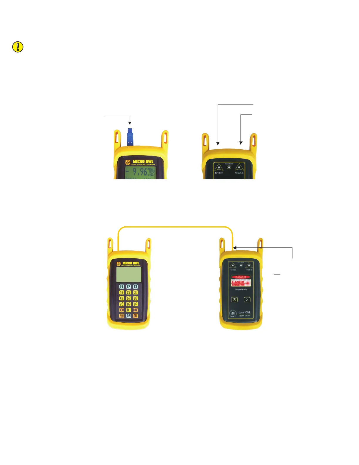
EQUIPMENT PORTS
Figure 1 shows the ports of the equipment used during this procedure. These ports may vary depending upon the
model of equipment.
VERIFY PROPER OPERATION OF THE EQUIPMENT
STEP 1 Connect the power meter and light source together with one of the patch cables as shown in Figure 2.
STEP 2 Power on the light source.
STEP 3 Power on the Micro OWL 2.
STEP 4 From the OPERATING MODE menu, select SIMPLE METER.
STEP 5 Press <F3> on the Micro OWL 2 until the wavelength reads 1310nm.
STEP 6 The Micro OWL 2 should read approximately -10.00 dBm. If the reading is below -12.00 dBm, the
patch cable should be replaced.
STEP 7 Once proper operation has been verified, remove the first patch cable from both units and set it aside.
STEP 8 Connect the second singlemode patch cable between the Micro OWL 2 and the Laser OWL as shown in
Figure 2.
Detector
Micro OWL 2 power meter
1310 nm
1550 nm
FIGURE 1
Test Equipment Ports
Laser OWL light source
FIGURE 2
Singlemode
Patch Cable
Connection
LIGHT SOURCE CONNECTOR
PORT NOTES:
– CONNECTOR TYPE MAY VARY
– DO NOT INSERT ANGLED
PHYSICAL CONTACT (APC)
CONNECTOR