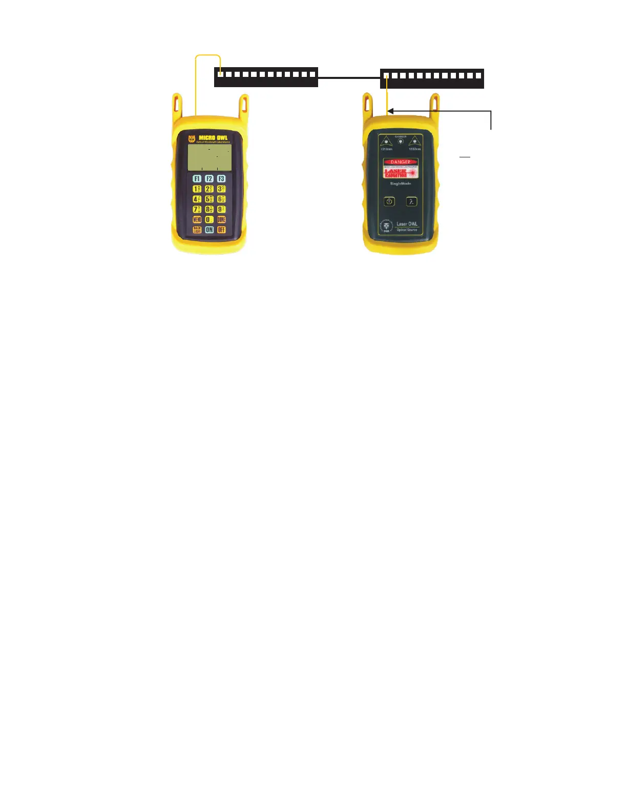
STEP 33 Connect the units to the first fiber to test as shown in Figure 3. Your readings will vary from the example
below.
STEP 34 Press <F2> to store the data point. If this is the first data point in the link, you may be prompted to enter
a new label.
STEP 35 Press <F3> to save the data point.
STEP 36 Disconnect the patch cables from the patch panels and move them to the next port in the patch panel,
then repeat steps 34 through 36 until all fibers in the link have been tested at 1310nm.
STEP 37 If also testing at 1550nm, repeat steps 33 through 36, but this time use the singlemode patch cable
attached to the 1550nm port. Also, make sure that you set the Micro OWL 2 and the Laser OWL to 1550nm.
1
2
3
4
5
6
7
8
9
10
11
12
1
2
3
4
5
6
7
8
9
10
11
12
FIGURE 3
Equipment
Connection for
Optical Loss
Measurements
UNITS
FIBER
FBR:1
_____________________
STORE
LINK #1
82
68%
dB
WAVE
1310nm
- 2 15x x
PASS BY 2 85X XX X
LIGHT SOURCE CONNECTOR
PORT NOTES:
– CONNECTOR TYPE MAY VARY
– DO NOT INSERT ANGLED
PHYSICAL CONTACT (APC)
CONNECTOR
 Loading...