13
3. INSTALLATION
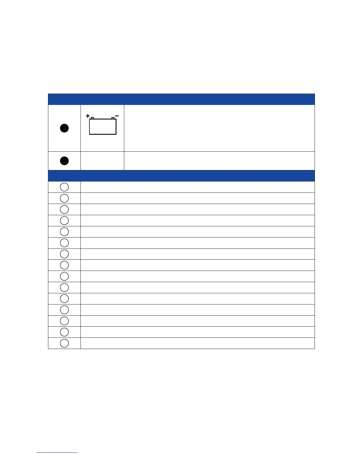
CONNECTION MARKINGS AT THE VISION CONTROL UNIT
Power converters with a rated voltage of 13.8 V and a minimum continuous power output of 6 Amps must be
used. We recommend using the power converter available from us.
Number Designation Explanation
1
31 / 30 / 15
Connect the power-supply cable provided here.
CAUTION!
Ensure that the other end of the power-supply cable is correctly connected
to the vehicle's electrical system. If polarity is reversed, the FeatureBox may
be destroyed!
2
ANT
Connect the antenna connector of the coaxial cable leading to the antenna
unit here.
Number Explanation
1
Antenna unit
2
Threaded elbow fitting
3
Mounting plate
4
SAT feed line; length 4.5 meter from external unit
5
Cable (black)
6
Ignition / terminal 15
7
Cable (red; battery positive)
8
Cable (brown; battery negative)
9
Fuses
10
Body battery
11
FeatureBox
12
Receiver satellite cable outlet; length 1.5 meters from FeatureBox
13
Receiver / TV with integrated receiver
14
2. TV set only with TWIN-LNB
15
Control Panel