PAC 212 Access Controller Install Guide
Legend for Wiring Diagram
1 RS-485 connection
2 Dipswitch for Reader voltage selector (12/24V or 5V, default = 12/24V)
3 RS-485 status LEDs
4 RS-232 status LEDs
5 Serial Number and Barcode
6 Door 1 LEDs
7 Reader
+V
LED
SIGA/SIGB
0V (tamper/DC - door contact)
0V (sounder)
0V
1 Red
2 Brown
3 White
4 Blue
5 Yellow
6 Black
8 Fail-Safe Lock
9 Request to Exit
RTE
0V
1 Blue
2 Black
10 Door 2 LEDs
11 One-Touch™ button
12 System status LED
13 Power Access
14 Battery Backup
15 DO NOT USE
16 12V/24V Power Supply Unit
VIN
0V
MSTAT
(Battery) +
(Battery) -
EARTH
1 Orange
2 White
3 Pink
4 Red
5 Black
6 Green/Yellow
17 USB
The USB pen must be compatible and FAT16 or FAT32 format (see TB224)
18 Future enhancement
19 Tamper Switch
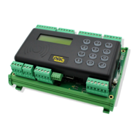
20 LCD Display
21 Keypad
- 3 -