081112-24 VISTA INSERT-C 9
Blower
The Insert comes equipped with a variable speed circu-
lating air blower. The blower system is thermostatically
controlled for automatic operation, as well manually with
a convenient bypass switch.
Blower Operation
Automatic: To operate the blower automatically, push
the rocker switch to the “0” or OFF position and set the
fan speed control to a desired setting.
This will allow the blower to turn on automatically once
the Insert has come up to operating temperature. It will
also shut the blower off after the re has gone out and
the appliance cooled to below a useful heat output range.
On and Off times will vary with installation and location
of appliance.
Manual: To manually operate the blower, push the rocker
switch to the “1” or ON position and set the fan speed
control to a desired setting. This will bypass the tempera-
ture switch and allow full control of the blower.
Suggested settings:
- Combustion air control setting of "L" (low), operate
blower speed control on “Low”.
- Combustion air control greater than "L" (low), oper-
ate blower speed control at desired setting.
Electrical Supply
Circulating air blower electrical rating: 115V, 60 Hz, 80
Watts.
For your protection against shock hazard, use only a
properly grounded outlet that will accept a three-pronged
plug. Do not cut or remove the grounding prong.
Consult local codes or in the absence of local codes, with
the current CSA C22.1 Canadian Electrical Code and in
the USA with the National Electrical Code, ANSI/NFPA
70 (latest edition).
Combustion Air
Consult local building codes regarding combustion air
supply. Intake or combustion air can be supplied to the
Insert in one of two ways:
1) Outside air supply: Remove cover from ash clean out
in existing replace. Place a rodent screen in place
of the cover. Install the Insert as described in the
"Installation" section, making sure not to cover the
opening of the air inlet. When installation is complete,
seal surround to replace and anywhere else air may
enter. This will ensure combustion air is drawn from
outside the house and into the 7" x 2" intake at the
lower rear of the appliance.
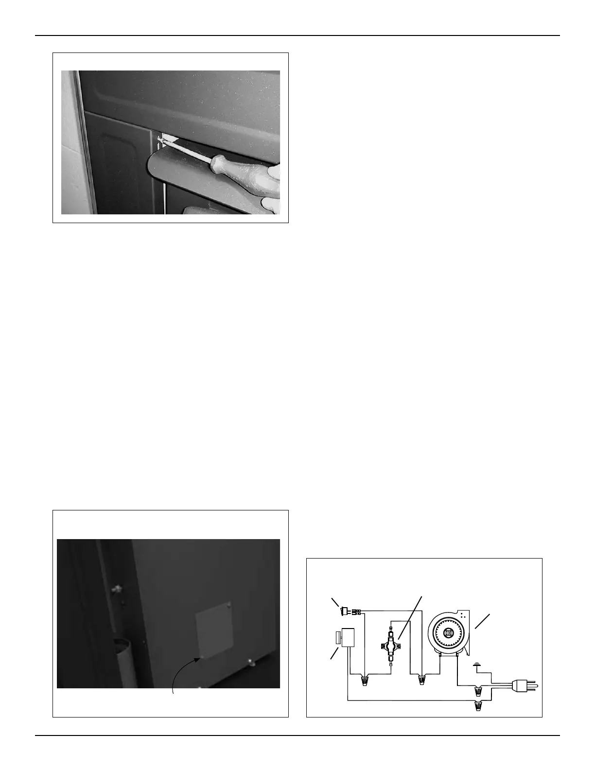
2) Room air supply: Remove the cover plate from either
casing side prior to installation (Fig. #14). Install the
Insert as described in the "Installation" section. The
Insert will now draw its air from the room through the
front.
Fig. # 13
Fig. # 14
Fig. # 15
L2 (black)
G (green)
L1 (white)
Speed
Control
Blower
Thermo
Switch
By-pass
Rocker Switch
Remove Screws & Cover
plate


 To Next Page
 Loading...