14
13
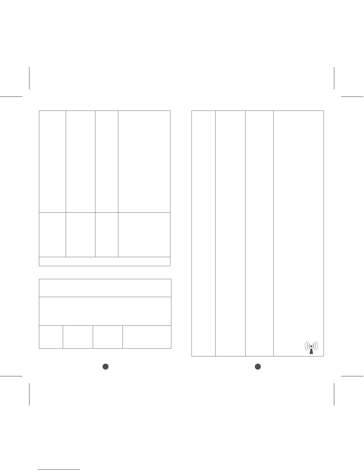
Guidance and manufacturer’s declaration – electromagnetic immunity
The models KTR-230 are intended for use in the electromagnetic
environment specified below. The customer or the user of the models
KTR-230 should assure that it is used in such an environment.
Immunity
test
IEC 60601
test level
Compliance
level
Electromagnetic
environment – guidance
Voltage
dips, short
interruptions
and voltage
variations
on power
supply
input lines
IEC
61000-4-11
Power
frequency
(50/60 Hz)
magnetic
field
IEC
61000-4-8
30 A/m 30 A/m
<5 % UT
(>95% dip
in U
T.)
for 0.5 cycle
40 % U
T
(60% dip
in U
T) for 5
cycles 70% U
T
(30% dip in UT)
for 25 cycles
<5% U
T
(>95 % dip in
U
T) for 5 sec
Mains power quality
should be that of a typical
commercial or hospital
environment. If the user of
the models KTR-230
requires continued
operation during power
mains interruptions, it is
recommended that the
models KTR-230 be
powered from an
uninterruptible power
supply or a battery.
Power frequency magnetic
fields should be at levels
characteristic of a typical
location in a typical
commercial or hospital
environment.
Not
applicable
NOTE U
T is the a.c. mains voltage prior to application of the test level
Conducted
RF
IEC
61000-4-6
Radiated
RF
IEC
61000-4-3
specifications
for
ENCLOSURE
PORT
IMMUNITY
to RF
wireless
communication
equipment
(Refer to
table 9 of
IEC
60601-1-2:
2014)
3 Vrms
150 kHz to
80 MHz
6 Vrms in
ISM
bands
10 V/m
80 MHz to
2.7 GHz
385MHz-
5785MHz
Test
specifications
for
ENCLOSURE
PORT
IMMUNITY
to RF
wireless
communication
equipment
(Refer to
table 9 of
IEC
60601-1-2:
2014)
Not
applicable
Not
applicable
10 V/m
80 MHz
to 2.7 GHz
385MHz-
5785MHz
Test
Portable and mobile RF
communications equipment
should be used no closer
to any part of the models
KTR-230, including cables,
than the recommended
separation distance
calculated from the
equation applicable to
the frequency of the
transmitter.
Recommended
separation distance
d=[3,5/V
1]×P
1/2
d=1.2×P
1/2
80 MHz
to 800 MHz
d=2.3×P
1/2
800 MHz
to 2.7 GHz
where P is the maximum
output power rating of the
transmitter In watts (W)
according to the transmitter
manufacturer and d Is the
recommended separation
distance in meters (m).
Field strengths from fixed
RF transmitters, as
determined by an
electromagnetic site survey,
a should be less than the
compliance level in each
frequency range.
b
Interference may occur In
the vicinity of equipment
marked with the following
symbol:
 Loading...