Do you have a question about the paladin Bradco VRS48 and is the answer not in the manual?
Covers general product information, service advice, and sound/vibration factors.
Emphasizes operator training, manual reading, and safety symbol identification.
Explains the meaning of DANGER, WARNING, CAUTION, and NOTICE signal words.
Provides fundamental safety rules for operation and maintenance.
Covers protection from debris, securing raised equipment, and hydraulic fluid hazards.
Addresses safe operation, maintenance, repair, and modification safety.
Covers checking utilities and general roller operation safety.
Details safety procedures for transporting and maintaining the equipment.
Illustrates the location of various decals on the vibratory roller.
Provides instructions on how to clean and apply safety decals.
Lists Bradco logo parts and model number identifiers.
Highlights key warnings for leaving the operator's seat and hydraulic system limits.
Details warnings related to high-pressure fluids and pinch hazards.
Emphasizes manual reading and warns against foot crushing hazards.
Provides general information and component identification for installation.
Describes the procedure for securely attaching the vibratory roller to the prime mover.
Warns about the serious injury risk from insecure attachment.
Outlines the steps for safely removing the vibratory roller.
Covers blocking the drum and essential shutdown steps before leaving the unit.
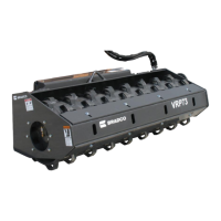
Introduces the roller's function and reminds operators to follow safety precautions.
Details the sequence of actions for operating the vibratory roller.
Highlights the value of regular maintenance and safety during service.
Lists routine checks and lubrication tasks required every 8 operating hours.
Provides specific safety instructions for detecting hydraulic fluid leaks.
Details maintenance tasks to be performed every 500 operating hours.
Step-by-step guide for changing the gear oil in the roller shaft.
Instructions for safely removing the vibratory roller drum assembly.
Crucial warning about preventing injury during drum removal.
Step-by-step guide for reinstalling the vibratory roller drum assembly.
Critical safety warning to avoid injury during drum installation.
Procedure for replacing the rubber vibration isolators.
Instructions for replacing bearings and hubs on the left side.
Advises against hub removal without supporting the roller shaft.
General safety reminder before performing maintenance.
Notes on handling heavy hubs and preventing shaft/drum damage.
Instructions for replacing bearings and hubs on the right side.
Continues instructions for right side bearing and hub replacement.
Notes regarding hub removal and the weight of hubs.
Procedure for replacing the hydraulic motor assembly.
Includes safety, gasket replacement, and updated motor notes.
Addresses issues with insufficient compaction and their solutions.
Covers problems with vibration, including no vibration and excessive noise.
Details solutions for oil leaks, drum rotation, and tilting issues.
Provides general torque values for fasteners when specific torques are not given.
Covers torque adjustments for plated bolts and metric specifications.
Diagram and measurements for vibratory roller dimensions.
Table detailing performance specs for smooth vibratory rollers.
Table detailing performance specs for padded vibratory rollers.
Defines excluded products and the duration of the limited warranty.
Outlines the conditions, claims process, and limitations of the warranty.
Diagram showing the components of the outer hub assembly.
Diagrams illustrating the components of the inner hub assemblies.
| Brand | paladin |
|---|---|
| Model | Bradco VRS48 |
| Category | Construction Equipment |
| Language | English |