• Stop watch
Measure elapsed time when determining flow rates
(crossflow and filtrate flux rate)
• Pipettes and sample tubes
Collect samples for analysis
• Beakers / reservoirs
To hold /collect sample, waste, etc.
• Graduated cylinders
For accurately determining collected volumes.
Installation
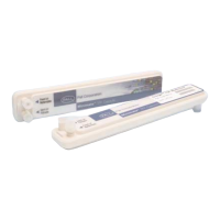
1. Remove the caps from the feed and retentate ports of
the Minimate TFF capsule.
Note: Do not discard caps. They are required for
storage.
2. Screw a male luer-to-hose-barb connector (included)
into each of the feed / retentate ports.
3. Cut a piece of tubing 3.2mm (1/8") i.d., long enough to
reach from the feed reservoir, through the pump head to
the capsule.
Note: Keep tubing lengths as short as possible to
reduce system hold-up volume.
4. Connect the tubing to the hose-barb on one of the feed
ports. Install the tubing in the pump head. Put the other
end of the tubing into the reservoir.
Note: If a pressure gauge or transducer is used,
connect the tubing to the pressure device. Then
connect the pressure device as close as possible
to the feed port using suitable connectors.
Note: Feed and retentate ports are interchangeable.
Depending on the orientation of the capsule, choose
the port that is at the lowest elevation as the feed
port. This allows for air to be easily expelled when
liquid is pumped through the capsule.
The recommended crossflow for the Minimate TFF
capsule is 30-40 mL/min.
5. Cut another piece of tubing, long enough to return from
the retentate port to the sample reservoir.
6. Attach the tubing to the retentate hose-barb and put the
other end in the reservoir. (Again, if a pressure gauge or
transducer is used, the tubing connects to the pressure
device, which must then be connected to the retentate
port.)
7. Place the retentate screw clamp on the retentate tubing
close to the retentate port (after the pressure gauge if
installed). Secure in place but do not tighten to restrict
the tubing.
8. Remove one of the filtrate caps.
9. Attach a female luer-to-hose-barb fitting to one of the
filtrate/vent ports.
Note: Depending on the orientation of the capsule,
choose the filtrate port that is at the highest elevation.
This allows air to be completely expelled from the
filtrate side of the membrane. The filtrate channel
can be drained easily by opening the other filtrate
port as a vent.
10.Attach a piece of tubing to the filtrate hose barb.
11.Install a tubing clamp over each piece of tubing where it
connects to the hose barb. Pinch the clamp to tighten.
Make sure the tubing is secure and does not easily pull
off the hose barb.
NOTE: Pall strongly recommends the use of pressure
gauges or transducers connected on both the feed
and retentate ports. If only one gauge is available, it
should be used on the feed port. The use of pressure
gauges allows accurate adjustment of feed pressures,
which provide for better reproducibility between
process runs. They can also help in the diagnosis of
system problems.
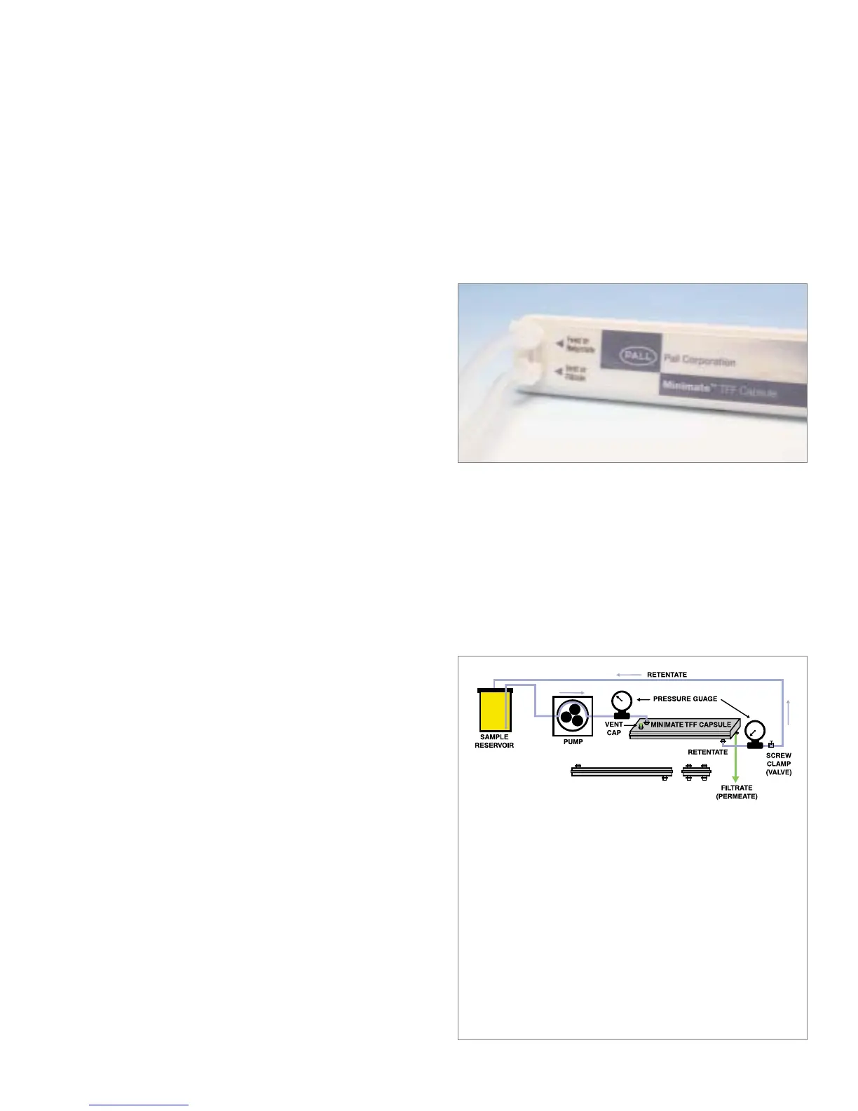
Figure 1
Typical Minimate
™
TFF Capsule set-up
The pump is connected with tubing between the process sample reservoir
and the feed port on the Minimate TFF capsule. Tubing connected to the
retentate port is returned to the reservoir. This allows flow of product across
(tangential to) the membrane surface to create a sweeping action that helps
prevent membrane fouling by reducing buildup of particles and product on
the surface. Pressure in this flow path, generated by the flow stream through
the channel and by restricting the tubing connected to the retentate port
with an adjustable clamp, is the driving force that creates liquid flow through
the membrane (filtrate flow rate). The average pressure applied to the
membrane is referred to as the transmembrane pressure (TMP). Increasing
the TMP increases the filtrate flow rate, up to a point. Applying too much
pressure will foul the membrane and reduce filtrate flow rate. Controlling the
TMP helps regulate the filtrate flow rate.
Tubing connected to one of the filtrate ports serves to carry the filtrate
(permeate) away from the device. The other filtrate port can be used as
a vent for draining all liquid in the tubing after the process is finished.
www.pall.com/lab
3