13
EN
USER MANUAL
speaker simulation DI box
passive
ilm
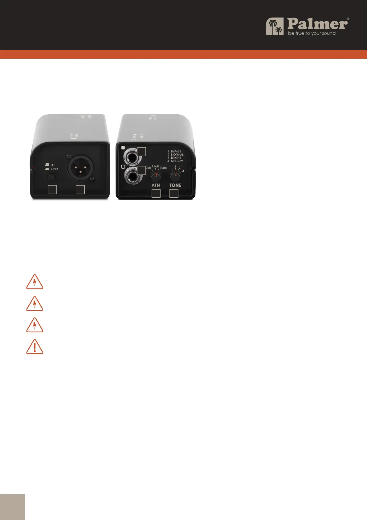
CONNECTIONS AND OPERATING ELEMENTS
1. INPUT
Audio input with 6.3mm jack socket.
A. Connect a guitar preamp using a shielded line cable.
B. Connect the speaker output of a guitar amplier using a speaker cable.
WARNING:Ampliers must not be operated in bridge mode on the speaker simulation box
.
WARNING:If an amplier is operated on the speaker simulation DI box, the ground
connection between input and output must be separated (switch no. 6 in the non-pressed LIFT position).
WARNING:The amplier output of a connected amplier must not exceed 120 W at 8 ohms!
ATTENTION: CAUTION when using a tube amplier: There is no load resistance
in the speaker simulation box! To prevent damage to the amplier, before switching on the amplier,
a suitable guitar loudspeaker or load resistor on the THRU jack socket must
be connected using a speaker cable!
2. THRU
The INPUT signal (INPUT) is output unchanged via the 6.3mm jack socket THRU.
3. ATT = attenuator
Rotary switch for adjusting the output level. Recommendation:
Connecting a guitar preamp (line signal): 0 dB attenuation
Connection of an practice amplier up to an output power of approx. 10 W: 15 dB attenuation
Connection of an amplier over 10 W output power (max. 120 W @ 8 ohms): 30 dB attenuation
4. TONE
Rotary switch for setting the sound characteristics of the output signal.
1 BYPASS: Sound unchanged at time of input signal
2 NORMAL: Standard sound setting
3 BRIGHT: Bright sound
4 MELLOW: Soft sound
2
1
3 4
6 5