180 Aquarea air-to-water heat pumps - Planning and installation manual - 02/2022
Installation
6
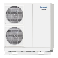
Installation example: Mono-bloc units WH-MDC09J3E5 and WH-MXF12J9E8
A
2
1
3
4
5
6
7
8
9
10
B
DC
1
2
3
12
a
11
13
10
9
8
7
6
5
A
L N L1
WARNING
ABCDEFGHJMFLG
ABCDEFGHJMFLG
ABCDEFGHJMFLG
ABCDEFGHJMFLG
POWERSUPPLY2POWERSUPPLY1
N1
B
CAUTION
240-250V
A WH-MDC09J3E5: Detailed view of the Rear Side
1 Rear side of the Cabinet
2 Cable gland for power cord 1
3 Cable gland for power cord 2
B WH-MDC09J3E5: Detailed view of the Front Side
4 Pump
5 Cable binder
6 Internal cable gland for power cord 1
7 Internal cable gland for power cord 2
8 Cable clamps / strain reliefs
9 RCCB for power supply 1
10 RCCB for power supply 2
C WH-MXF12J9E8: Detailed view of the Rear Side
1 Rear side of the Cabinet
2 Cable gland for power cord 1
3 Cable gland for power cord 2
11 Cable gland for remote controller cable
12 Cable gland for optional accessory cables
D WH-MXF12J9E8: View of the Front Side
5 Cable binder
8 Cable clamps / strain reliefs
9 RCCB for power supply 1
10 RCCB for power supply 2
13 Main PCB
a Cut cable sleeve crosswise
Connection diagram – Mono-bloc units
Models Connection diagram
WH-MDC**J3E5
WH-MDC**H6E5
WH-MXC**J*E5
WH-MXC**H*E5
WH-MHF**G*E5
Terminals on
mono-bloc unit
Terminals on
disconnector
Power supply 2Power supply 1
L
1
N
1
L
1
N
L N
L N
1
WH-MXC09J3E8
WH-MXC09H3E8
Terminals on
mono-bloc unit
Terminals on
disconnector
Power supply 2Power supply 1
L
A1
L
A2
L
A3
L
A1
L
A2
L
A3
N
L
L
N
N
WH-MXC**J9E8
WH-MXC**H9E8
Terminals on
mono-bloc unit
Terminals on
disconnector
Power supply 2Power supply 1
A1
L
A2
L
A3
N
L
L
A1
L
A2
L
A3
N
L
C1
L
C2
L
C3
N
L
C1
L
C2
L
C3
N
 Loading...