158 Aquarea air-to-water heat pumps - Planning and installation manual - 01/2018
Installation
159
Aquarea air-to-water heat pumps - Planning and installation manual - 01/2018
Installation
Connections of the coolant pipelines – outdoor units
2
1
4
3
5
1 Front plate
2 Pipe collimators
3 Impermissible location to place
the adjustable spanner
4 Correct location to place the
adjustable spanner
5 Thermal insulation or putty
knife
Permissible tightening torques of the coolant pipelines – outdoor units
Model Note Refrigerant - hot gas pipeline Coolant - uid pipeline
Diameter
mm (inches)
Torque
Nm
Diameter
mm (inches)
Torque
Nm
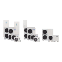
LT
WH-ADC0309H3E5(B) + WH-UD03HE5-1 1
12.7 (1/2) 55
6.35 (1/4) 18
WH-ADC0309H3E5(B) + WH-UD05HE5-1 1
WH-ADC0309H3E5(B) + WH-UD07HE5-1
15.88 (5/8) 65
WH-ADC0309H3E5(B) + WH-UD09HE5-1
WH-ADC1216H6E5 + WH-UD12HE5
9.52 (3/8) 42
WH-ADC1216H6E5 + WH-UD16HE5
WH-ADC0916H9E8 + WH-UD09HE8
WH-ADC0916H9E8 + WH-UD12HE8
WH-ADC0916H9E8 + WH-UD16HE8
WH-SDC03H3E5-1 + WH-UD03HE5-1
12.7 (1/2) 55
6.35 (1/4) 18
WH-SDC05H3E5-1 + WH-UD05HE5-1
WH-SDC07H3E5-1 + WH-UD07HE5-1
15.88 (5/8) 65
WH-SDC09H3E5-1 + WH-UD09HE5-1
WH-SDC12H6E5 + WH-UD12HE5
9.52 (3/8) 42
WH-SDC16H6E5 + WH-UD16HE5
WH-SDC09H3E8 + WH-UD09HE8
WH-SDC12H9E8 + WH-UD12HE8
WH-SDC16H9E8 + WH-UD16HE8
6.6.2 Connecting coolant pipelines to the outdoor unit
WARNING
Danger to life from electric shock
The devices are operated with 230-V or 400-V alternating current. Touching the live electrical
cables can be life-threatening due to electrical shock.
► Before opening the outdoor unit, make sure that the entire system (including hy-
dro-module or combination hydro-module, tank and E-heating element) is disconnect-
ed from the electric supply.
!
IMPORTANT
The pipelines can be installed in four directions from the device: front, back, to the right and to
the left. Select the direction most suitable for the installation location.
Carry out the following steps to connect prepared coolant pipelines coming from the indoor unit
to the outdoor unit:
1. Open the outdoor unit (→ 6.5 Opening devices, p. 148).
2. Remove the selected pipe collimator (2) and provide it with suitable holes for the
pipelines.
3. Reassemble the pipe collimator so that rain will not enter the outdoor unit.
4. Align the tube and valve centrally and rst pull the cap nut by hand and then with a torque
wrench and an adjustable spanner to counter it. Ensure the correct torques (→ Permissi-
ble tightening torques of the coolant pipelines - outdoor units, p. 159).
5. Lock the pipe entries into the outdoor unit using thermal insulation or putty knife (provided
on site) to ensure that no gap is left.
 Loading...