Do you have a question about the Panasonic AV-HS400AN and is the answer not in the manual?
Covers CAUTION, WARNING, and FCC compliance notices for safe operation.
Lists crucial instructions for safe operation, handling, and maintenance.
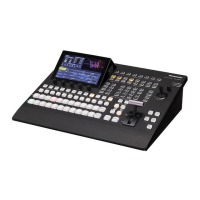
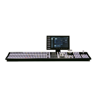
Describes the main control panel layout, power, and alarm indicators.
Explains the LCD screen for menu navigation and parameter adjustment.
Illustrates and describes the various input and output connectors on the rear panel.
Covers LAN, RS-422, GPI, Tally connectors, ground, and AC power connections.
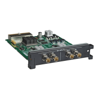
Shows the system configuration diagram and lists optional boards.
Illustrates connection examples for gen-lock operation with frame synchronizer off.
Illustrates connection examples for gen-lock operation with frame synchronizer on.
Explains selecting background sources and bus modes for transitions.
Details selecting source signals for background transitions using crosspoint buttons.
Describes how to choose between A/B and Flip-flop (PGM/PST) bus modes.
Explains how to choose between MIX and WIPE transition modes.
Details using the fader lever for manual transitions and understanding tally LEDs.
Explains how to set and execute automatic transitions using the AUTO button.
Describes how to perform an instant cut transition.
Introduces wipe operations and pattern selection.
Guides on selecting wipe patterns using buttons and pattern pages.
Explains how to set the direction (normal/reverse) for wipe transitions.
Introduces key operations, including definition and edge addition.
Details how to select Luminance, Linear, Chroma, or Full key types.
Explains how to select key fill and source signals, and set fill matte color.
Guides on setting key transition types, time, and direction.
Details how to adjust key definition parameters like clip, gain, and density.
Explains how to set up and adjust chroma key parameters using auto sampling.
Continues chroma key adjustment with Hue-Rad, Sat-Rad, Soft, and Cancel parameters.
Introduces combining a sub-screen image with the background.
Explains how to select the source signal for the PinP image.
Details setting transition times and executing PinP fade-in/fade-out.
Covers adjusting PinP position, size, and dot-by-dot mode.
Introduces combining images using downstream key effects.
Explains how to choose between Luminance and Linear DSK types.
Covers selecting DSK fill and source signals, and setting fill matte color.
Details setting transition times and executing DSK fade-in/fade-out.
Explains how to adjust DSK definition parameters like clip, gain, and density.
Describes how to fade the program image to black or fade in from black.
Describes storing and recalling panel settings like crosspoint, transition, and wipe configurations.
Explains how to store, recall, and clear panel settings in the preset memory.
Covers configuration of SDI and analog input signals.
Explains how to enable or disable the frame synchronizer for each input.
Details selecting input modes (Normal, D by D, UC, Auto) for different signal formats.
| Type | Video Switcher |
|---|---|
| Audio Mixing | Yes |
| Video Inputs | 4 x HD/SD-SDI, 4 x HDMI |
| Video Outputs | 4 x HD/SD-SDI, 1 x HDMI |
| Audio Outputs | 2 x XLR |
| Effects | Transitions |
| Control | Ethernet RS-422 |
| Format Support | HD/SD |
| Weight | 10 kg |