Do you have a question about the Panasonic AV-HS450 and is the answer not in the manual?
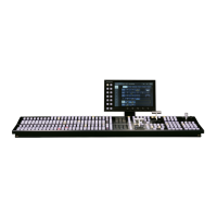
Instructions for installing and connecting the control panel, including power and location.
Instructions for installing and connecting the mainframe, including power, rack mounting, and location.
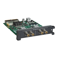
Procedure for installing optional boards into the mainframe slots, including safety precautions.
Details on connecting the system components, including block diagrams and specific scenarios.
Provides a block diagram illustrating the connections between the mainframe and control panel.
Illustrates connections for gen-lock operation with the frame synchronizer off.
Illustrates connections when the frame synchronizer is on, including optional boards.
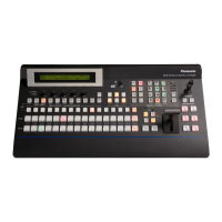
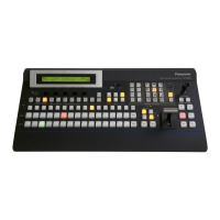
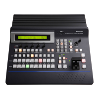
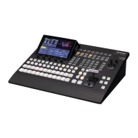
Overview of the control panel layout, including indicators and key operational areas.
Explains the function of PGM/A, PST/B, and AUX bus crosspoint buttons and selectors.
Describes selection of wipe patterns and memory operations for storing/recalling data.
Explains the assignment of functions to user buttons for customized operations.
Details the functions of transition buttons like BKGD, KEY, MIX, WIPE, AUTO, CUT.
Describes the LCD menu structure and delegation functions for various settings.
Explains the use of the positioner and rotary encoder for adjusting key and PinP parameters.
Details the SD memory card slot and access LED, and recommends compatible cards.
Identifies and describes the rear panel connectors on the control panel.
Details the front and rear panel components of the mainframe unit.
Explains the front panel controls of the mainframe, including power switches and indicators.
Identifies and describes the rear panel connectors on the mainframe.
Covers selecting buses, modes, and executing manual, auto, or cut background transitions.
How to select input signals for background transitions using crosspoint buttons.
Utilizes the SHIFT function to switch between front and rear materials for crosspoint buttons.
Setting the A/B bus system or flip-flop (PGM/PST) system from the setting menu.
How to select MIX or WIPE transition modes for background and key transitions.
Operation of the fader lever for manual transitions and its effect on auto transition.
Executing transitions automatically using the transition time set in the TIME menu.
Performing an instant transition by pressing the CUT button.
Covers setting and executing IMAGE effects like paint, mosaic, and defocus.
Setting paint, mono-color, mosaic, and defocus effects for bus materials.
How to activate and execute the IMAGE effect, noting a one-frame delay.
Details selecting wipe patterns, backgrounds, directions, decorations, and modifying wipes.
Selecting background and key transition patterns using wipe pattern selector buttons.
Selecting still images, color background, or black for the 3D2 pattern page background.
Selecting the direction (normal, reverse, or N/R) for background wipe transitions.
Adding borders, shadows, or soft effects to background wipe transitions, including color settings.
Setting the start position for WIPE and SQ patterns using positioners or menu items.
Adding lighting effects to specific wipe patterns for background and key transitions.
Covers key types, material selection, transitions, preview, adjustments, decorations, masking, and flying key.
Choosing key types like Lum, Chroma, Full, or Linear for key signal generation.
Selecting key fill and key source signals using AUX bus buttons or CONFIG menu.
Selecting transition modes (MIX/WIPE) and directions for key transitions.
Outputting key preview images and adjusting keys before final execution.
Adjusting clip, gain, density, and invert settings for luminance and linear keys.
Executing sampling automatically or manually to adjust chroma key parameters.
Adding borders, shadows, or outlines to keys, including edge color settings.
Masking key signals using box patterns to define the effective area for key combination.
Using DVE effects to move, expand, or contract key signals for flying key transitions.
Covers selecting PinP channels, materials, shapes, transitions, adjustments, decorations, and trimming.
Selecting PinP channels and materials for combining images.
Choosing Square or Circle shape for PinP images and adjusting aspect ratio.
Setting whether to output PinP preview images to the preview output.
Setting transition times and executing fade-in/fade-out for PinP images.
Adjusting PinP position and size using positioner or menu items.
Performing symmetrical operations for PinP1 and PinP2 axes, setting priority and reference.
Adding borders or soft effects to PinP images, including border color settings.
Setting trimming types and values for PinP images to adjust aspect ratio or margins.
Covers DSK types, channel/material selection, transitions, preview, adjustments, decorations, and masking.
Choosing DSK types like Lum, Chroma, Full, or Linear for key signal generation.
Selecting DSK channels and fill materials using AUX bus buttons or CONFIG menu.
Setting transition times and executing fade-in/fade-out for DSK images.
Setting whether to output DSK preview images to the preview output.
Adjusting clip, gain, density, and invert settings for DSK.
Adding borders, shadows, or outlines to DSK, including edge color settings.
Masking DSK signals using box patterns to define the effective area for DSK combination.
Fading out to a black screen or fading in from a black screen with adjustable transition duration.
Setting the internal color background using hue, saturation, luminance, or preset colors.
Setting the color background using Hue, Sat, Lum adjustments or preset colors.
Covers selecting AUX output materials, AUX1 transitions, and enabling/disabling AUX transitions.
Selecting output materials for AUX1 to AUX4 using AUX bus selector and crosspoint buttons.
Executing MIX transitions for AUX1 output by switching output signals.
Setting the transition time and enabling or disabling AUX1 transitions.
Covers memory registration, recall, storage, deletion, and effect dissolve.
Lists materials, transitions, and patterns that can be stored/recalled in SHOT, BKGD/WIPE, PinP, CAM memories.
Procedure for storing images or operations into memory using number keys and memory type buttons.
Procedure for recalling stored operations from memory using number keys and memory type buttons.
Procedure for deleting stored operations from memory using number keys and memory type buttons.
Performing smooth switching between current image and stored operations using SHOT memory.
Covers transferring images from AUX bus and saving images to flash memory.
Importing still images from AUX bus to internal frame memories (FMEM1-4).
Saving frame memory data to the mainframe's flash memory for retention when power is off.
Covers initializing, saving, loading, deleting files, and displaying information for SD memory cards.
Formatting SD/SDHC memory cards to prepare them for use in the unit.
Saving frame memory data or setup data onto SD memory cards.
Loading frame memory or setup data from SD memory cards into the unit.
Deleting specific files (still image or setup data) from SD memory cards.
Showing the number of images and free space available on the SD memory card.
Covers frame synchronizer, input mode, freezing, color corrector, up-converter, and analog/DVI settings.
Enabling or disabling the frame synchronizer for each input signal, except for DVI.
Setting input modes (Normal, D by D, UC, Auto) for HD signals based on system format.
Freezing input signals frame by frame or field by field for display.
Enabling the color corrector to adjust colors of input signals for IN9 to IN16.
Configuring up-converter settings for specific inputs and scaling methods (SQ, EC, LB).
Setting the input signal gain for analog input boards using AnaGain item.
Adjusting chroma, pedestal, and hue levels for analog composite input signals.
Setting DVI input signals by selecting signal system (Dig/Ana) and resolution.
Setting DVI input signals by selecting signal system (Dig/Ana) and resolution.
Adjusting clock/phase and horizontal/vertical position of DVI-I input signals.
Assigning output signals to connectors and setting output modes.
Assigning output signals (PGM, PVW, CLN, AUX, KeyOut) to output connectors.
Setting DVI output signals by selecting signal system, resolution, and scaling method.
Configuring down-converter settings for SDI output boards, including scaling and delay.
Selecting external or internal sync signals (BBST, BBAD, TRI, INT) for system synchronization.
Adjusting H-phase and V-phase of output video signals relative to the system REF signal.
Covers screen layouts, split frame/character settings, tally displays, and material name changes.
Configuring multi view display modes (16, 10, 9, 4 split) and assigning inputs to subscreens.
Setting split frame brightness, character display, and background for multi view displays.
Superimposing tally displays (red/green) onto split frames of the multi view display.
Changing names of input materials displayed on the multi view display (default, preset, user).
Enabling high-resolution output for DVI-D on OUT5/OUT6 when the system mode is SD.
Superimposing menu screens onto preview or multi view outputs for display.
Setting passage of V ancillary data and embedded audio data through the SDI input signals.
Selecting the system's video format (e.g., 1080/59.94i) and 16:9 squeeze mode.
Assigning signals to crosspoints and setting the timing for switching them.
Assigning external video input and internal signals to crosspoint buttons 1 to 32.
Setting the timing for switching crosspoints (Any, Field1, Field2) for live or editing applications.
Assigning various functions to six user buttons for customized operations.
Assigning various functions to six user buttons for customized operations.
Setting the date and time for SD memory card timestamps.
Configuring IP address, subnet mask, and viewing MAC address for LAN connection.
Setting LCD backlight behavior and enabling/disabling menu delegation function.
Enabling/disabling control of external devices (editor, pan-tilt head) via RS-422.
Enabling or disabling control of external devices (editor, pan-tilt head) via RS-422.
Lists functions controllable by an editor controller (AG-A850) via RS-422 protocol.
Setting functions controllable from GPI ports and enabling/disabling control for each port.
Displays alarm statuses and alarm messages for power supply and cooling fan.
Displaying alert statuses for power supply and cooling fan on the LCD.
Displays alarm messages on LCD, detailing trouble type and recommended operation.
Shows software/hardware versions of the unit and connected optional boards.
Resets setting data to factory defaults and initializes the fader lever range.
Resets all set data to factory shipment status, excluding network and date/time.
Initializes the fader lever range for transitions when it fails to complete.
Instructions for connecting the control panel and mainframe using the CAT5E cable.
Details LAN, EDITOR, COM, and TALLY/GPI connectors on the mainframe.
Connecting a host computer to the mainframe's LAN connector for image transfer.
Pin assignments for connecting an external device to the EDITOR connector for control.
Pin assignments for connecting Panasonic pan-tilt head systems to the COM connector.
Details the TALLY/GPI connector pinout for input, output, and alarm signals.
Details the TALLY/GPI connector pinout on the control panel.
Details the TALLY/GPI connector pinout on the control panel for input, output, and alarm signals.
Step-by-step guide for installing the HS450 Tool image transmission software.
Describes how to operate the HS450 Tool software, including startup, exit, and IP address settings.
Steps for selecting mode, destination, image file, size, and aspect ratio for transmission.
Steps for selecting mode and images to import from the unit to the host computer.
| Aux Buses | 4 |
|---|---|
| Keyers | 4 |
| Frame Memories | 2 |
| Multi-viewer | Yes |
| Video Inputs | 16 SDI inputs |
| Audio Inputs | 16 channels embedded in SDI |
| Control Interface | Ethernet, RS-422 |
| Video Formats | 1080i, 720p |
| Transition Effects | Mix, Wipe |