2
8 Wiring Connection Diagram---------------------------------18
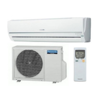
8.1. CS-A7HKD CU-A7HKDCS-A9HKD CU-
A9HKD------------------------------------------------------ 18
8.2. CS-A12HKD CU-A12HKD ----------------------------19
9 Electronic Circuit Diagram-----------------------------------20
10 Printed Circuit Board ------------------------------------------21
10.1. Main Printed Circuit Board-----------------------------21
10.2. Power Printed Circuit Board---------------------------22
10.3. Indicator Printed Circuit Board------------------------23
10.4. Patrol Printed Circuit Board ---------------------------23
11 Installation Instruction ----------------------------------------24
11.1. Select The Best Location ------------------------------24
11.2. Indoor/Outdoor Unit Installation Diagram ---------- 24
11.3. Indoor Unit ------------------------------------------------- 25
11.4. Outdoor Unit-----------------------------------------------28
12 Operation Control----------------------------------------------- 31
12.1. Heating Operation----------------------------------------31
12.2. Cooling Operation---------------------------------------- 32
12.3. Soft Dry Operation --------------------------------------- 33
12.4. Automatic Operation-------------------------------------34
12.5. Indoor Fan Speed Control -----------------------------35
12.6. Outdoor Fan Speed Control ---------------------------37
12.7. Vertical Airflow Direction Control--------------------- 37
12.8. Horizontal Airflow Direction Control -----------------38
12.9. Powerful Operation -------------------------------------- 38
12.10. Quiet Operation------------------------------------------- 39
12.11. Timer Control---------------------------------------------- 41
12.12. Random Auto Restart Control-------------------------41
12.13. Remote Control Signal Receiving Sound ----------41
12.14. Patrol Operation------------------------------------------42
12.15. e-ion Operation -------------------------------------------45
13 Protection Control ----------------------------------------------47
13.1. Restart Control (Time Delay Safety Control) ----- 47
13.2. 7 Minutes Time Save Control------------------------- 47
13.3. 60 Seconds Forced Operation ----------------------- 47
13.4. Starting current Control--------------------------------- 47
13.5. Freeze Preventive Control ---------------------------- 47
13.6. Compressor Reverse Rotation Protection
Control------------------------------------------------------ 48
13.7. Dew Prevention control -------------------------------- 48
13.8. 30 Minutes Time Save Control ----------------------- 48
13.9. Compressor Overload Protection Control --------- 49
13.10. 4-Way Valve Control ------------------------------------ 49
13.11. Outdoor Fan Motor Control---------------------------- 49
13.12. Hot Start Control ----------------------------------------- 49
13.13. Cold Draft Prevention Control ------------------------ 49
13.14. Deice Control --------------------------------------------- 50
14 Servicing Mode-------------------------------------------------- 52
14.1. Auto OFF/ON Button ----------------------------------- 52
14.2. Select Remote Control Transmission Code------- 52
14.3. Remote Control Button--------------------------------- 53
15 Troubleshooting Guide--------------------------------------- 54
15.1. Refrigeration cycle system ---------------------------- 54
16 Disassembly and Assembly Instructions -------------- 56
16.1. Indoor Electronic Controllers and Control
Board Removal Procedures -------------------------- 56
16.2. Indoor Fan Motor and Cross Flow Fan
Removal Procedures ----------------------------------- 58
17 Technical Data --------------------------------------------------- 60
17.1. Thermostat Characteristics---------------------------- 60
17.2. Operation Characteristics ----------------------------- 61
18 Exploded View and Replacement Parts List----------- 73
18.1. Indoor Unit------------------------------------------------- 73
18.2. Outdoor Unit ---------------------------------------------- 75
1 Safety Precautions
• Read the following “SAFETY PRECAUTIONS” carefully before perform any servicing.
• Electrical work must be installed or serviced by a licensed electrician. Be sure to use the correct rating of the power plug and
main circuit for the model installed.
• The caution items stated here must be followed because these important contents are related to safety. The meaning of each
indication used is as below. Incorrect installation or servicing due to ignoring of the instruction will cause harm or damage, and
the seriousness is classified by the following indications.
• The items to be followed are classified by the symbols:
• Carry out test run to confirm that no abnormality occurs after the servicing. Then, explain to user the operation, care and
maintenance as stated in instructions. Please remind the customer to keep the operating instructions for future reference.
This indication shows the possibility of causing death or serious injury.
This indication shows the possibility of causing injury or damage to properties.
This symbol denotes item that is PROHIBITTED from doing.
 Loading...