EasyManua.ls Logo

Panasonic CS-A7GKD

Panasonic CS-A7GKD
81 pages
To Next Page IconTo Next Page
Loading...
© 2006 Panasonic HA Air-Conditioning (M) Sdn. Bhd.
(11969-T). All rights reserved. Unauthorized copying and
distribution is a violation of law.
Order No. MAC0611059C8
Air Conditioner
CS-A7GKD CU-A7GKD
CS-A9GKD CU-A9GKD
CS-A12GKD CU-A12GKD
TABLE OF CONTENTS
PAGE PAGE
1 Safety Precautions----------------------------------------------- 2
2 Specifications ----------------------------------------------------- 4
2.1. CS-A7GKD CU-A7GKD---------------------------------- 4
2.2. CS-A9GKD CU-A9GKD---------------------------------- 6
2.3. CS-A12GKD CU-A12GKD ------------------------------ 8
3Features------------------------------------------------------------10
4 Location of Controls and Components ------------------11
4.1. Product Overview-----------------------------------------11
5Dimensions------------------------------------------------------- 12
5.1. Indoor Unit & Remote Control ------------------------ 12
5.2. Outdoor Unit----------------------------------------------- 13
6 Refrigeration Cycle Diagram-------------------------------- 14
7 Wiring Connection Diagram--------------------------------- 17
7.1. CS-A7GK CU-A7GK / CS-A9GK CU-A9GK------- 17
7.2. CS-A12GK CU-A12GK --------------------------------- 18
8 Electronic Circuit Diagram----------------------------------- 19
Question and Answer IconNeed help?

Do you have a question about the Panasonic CS-A7GKD and is the answer not in the manual?

Panasonic CS-A7GKD Specifications

General IconGeneral
BrandPanasonic
ModelCS-A7GKD
CategoryAir Conditioner
LanguageEnglish

Summary

Safety Precautions

Specifications

CS-A7 GKD CU-A7 GKD Specifications

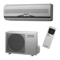
Detailed technical specifications for the CS-A7GKD/CU-A7GKD model.

CS-A9 GKD CU-A9 GKD Specifications

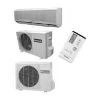
Detailed technical specifications for the CS-A9GKD/CU-A9GKD model.

CS-A12 GKD CU-A12 GKD Specifications

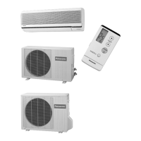
Detailed technical specifications for the CS-A12GKD/CU-A12GKD model.

Features

Location of Controls and Components

Product Overview

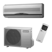
Illustrates the layout and key parts of the indoor and outdoor units.

Dimensions

Indoor Unit & Remote Control Dimensions

Physical dimensions and layout for the indoor unit and remote control.

Outdoor Unit Dimensions

Physical dimensions and installation space requirements for the outdoor unit.

Refrigeration Cycle Diagram

Block Diagrams

CS-A7 GKA9 GK Block Diagram

Electrical block diagram for CS-A7GK and CS-A9GK models.

CS-A12 GK Block Diagram

Electrical block diagram for the CS-A12GK model.

Wiring Connection Diagrams

CS-A7 GKA9 GK Wiring Diagram

Detailed wiring schematic for CS-A7GK and CS-A9GK models.

CS-A12 GK Wiring Diagram

Detailed wiring schematic for the CS-A12GK model.

Electronic Circuit Diagram

Printed Circuit Board Details

Indoor Main PCB

Top and bottom view of the indoor unit's main printed circuit board.

Indoor Power PCB

Top and bottom view of the indoor unit's power printed circuit board.

Indicator PCB

Details of the indicator board's components and layout.

Installation Instructions

Location Selection

Guidance on choosing optimal indoor and outdoor unit placement for performance.

Indoor Unit Installation Procedures

Detailed steps for mounting the indoor unit and preparing for piping.

Indoor Unit Connection Procedures

Steps for connecting the indoor unit's power and communication cables.

Outdoor Unit Installation and Piping

Guidance on mounting outdoor unit, connecting pipes, and evacuation.

Operation and Control

Heating Operation

Details on how to operate the unit in heating mode for comfort.

Cooling Operation

Procedures for operating the unit in cooling mode to lower room temperature.

Soft Dry Operation

Information on the soft dry mode for dehumidification and gentle cooling.

Automatic Operation

How the unit automatically selects the optimal operating mode based on conditions.

Advanced Operation Controls

Details on safety controls, timing, special modes like freeze prevention, and deicing.

Indoor Fan Speed Control

Fan Speed Charts and Modes

Charts for fan speed rotation and automatic fan speed control logic.

Airflow Direction Control

Vertical Airflow Control

Details on auto and manual control for vertical airflow direction.

Horizontal Airflow Control

Information on adjusting horizontal airflow direction.

Powerful Operation

Quiet Operation

Timer and Control Functions

Patrol and e-ion Operation

Patrol Operation

How the unit monitors air quality and activates e-ion purification.

e-ion Operation

Explanation of the e-ion air purifying system's operation and control.

Servicing Modes

Auto OFFON Button Function

Using the Auto OFF/ON button for operation modes and test runs.

Remote Control Transmission Code Selection

Procedure to select remote control transmission codes to prevent interference.

Remote Control Button Functions

Explains various buttons and their functions on the remote control.

Troubleshooting Guide

Refrigeration Cycle System Issues

Diagnosing issues related to refrigerant pressure, temperature, and component malfunctions.

Disassembly and Assembly Instructions

Indoor Unit Control Board Removal

Step-by-step guide for removing the indoor unit's electronic control board.

Indoor Fan Motor Removal

Procedures for removing the indoor fan motor and cross-flow fan assembly.

Technical Data

Thermostat Characteristics

Graphs showing thermostat behavior in cooling, soft dry, and heating modes.

Operation Characteristics

Performance data graphs for cooling and heating based on temperature and piping length.

Exploded View and Replacement Parts List

Indoor Unit Parts List

Detailed list and diagram of all replaceable parts for the indoor unit.

Outdoor Unit Parts List

Detailed list and diagram of all replaceable parts for the outdoor unit.

Related product manuals