– 21 –
MAC9512086C2
CS-C181KE
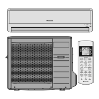
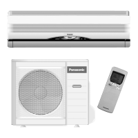
Installation Information
Indoor / Outdoor unit installation diagram
Length of power supply cord Piping direction Attention not to bend up drain hose
<
<
<
<
about 1 m
about 2 m
Right
rear
Right bottom
Left
rear
Left bottom
Left
(Front side)
Right
Installation parts you must
purchase (*)
Installation plate 1
Sleeve (*)
Bushing-Sleeve (*)
Putty (Gum Type Sealer) (*)
Bend the pipe as closely on the
wall as possible, but be careful
that it doesn’t break.
Vinyl tape (Wide) (*)
• Apply after carrying out a
drainage test.
• To carry out the drainage
test, remove the air filters
and pour water into the heat
exchanger.
Saddle (*)
Connecting cable
(3-CORE WIRE/2.5 mm
2
)
Locally approved cable.
Vinyl tape (*)
(Narrow)
• This illustration is for explanation purposes only.
The indoor unit will actually face a different way.
Additional drain hose (*)
• Carry out insallation
after checking for gas
leaks.
• After securing with
three of the vinyl
tape 3, wrap with
vinyl tape 4.
Vinyl tape
4
Vinyl tape 3
Air purifying filter !
(Left and right are identical)
1/4" Liquid side piping (*)
Gas side piping 1/2" or 5/8" (*)
5 cm or
more
5 cm or
more
100 cm
or more
10 cm
or more
10 cm
or more
Insulation of piping connection
Attaching the remote control holder to the wall
Untitled-3 6/19/00, 5:19 PM21