1 Safety Precautions 3
2 Features
5
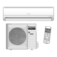
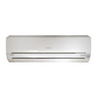
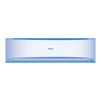
2.1. Wall Type
6
2.2. Duct Type
9
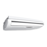
2.3. Ceiling Floor Type
12
2.4. Mini-Cassette Type
14
3 Product Specifications
16
3.1. Wall Type
16
3.2. Duct Type
17
3.3. Ceiling Floor Type
18
3.4. Mini-Cassette Type
19
3.5. Outdoor unit: CU-3E18EBE
20
4 Dimensions
21
4.1. Wall Type
21
4.2. Duct Type
23
4.3. Ceiling Floor Type
25
4.4. Mini-Cassette Type
26
4.5. Outdoor Unit
27
5 Refrigeration Cycle Diagram
28
6 Wiring Diagram
29
6.1. Wall Type
29
6.2. Duct Type
30
6.3. Ceiling Floor Type
31
6.4. Mini-Cassette Type
32
6.5. Outdoor Unit
33
7 Electronic Circuit Diagram
34
8 Operation Details
36
8.1. Wall Type
36
8.2. Duct Type
53
8.3. Ceiling Floor Type
59
8.4. Mini-Cassette Type
73
8.5. Outdoor Unit Operation
87
8.6. Forced Cooling Operation Control
88
8.7. Wiring Error Check Control
89
8.8. Outdoor Unit - Check Point
90
9 Self Diagnosis Display
91
9.1. Breakdown Self Diagnosis Function (Three Digits
Alphanumeric Code)
91
9.2. Error Code
92
10 Installation Information
96
11 Installation Instructions
97
12 Disassembly of Parts
108
12.1. Wall Type
108
12.2. Duct Type
110
12.3. Ceiling Floor Type
112
12.4. Mini-Cassette Type
113
12.5. Outdoor Unit
115
13 Technical Data
117
13.1. Operation Characteristics
117
14 Exploded View and Replacement Parts List
119
14.1. Wall Type
119
14.2. Duct Type
125
14.3. Ceiling Floor Type
127
14.4. Mini-Cassette Type
129
14.5. Outdoor Unit
134
CONTENTS
Page Page
2
 Loading...