EasyManua.ls Logo

Panasonic CS-PS9NKV User Manual

Panasonic CS-PS9NKV
108 pages
To Next Page IconTo Next Page
Page #1 background imageLoading...
Page #1 background image
© Panasonic Appliances Air-Conditioning (M) Sdn. Bhd. 2012.
Unauthorized copying and distribution is a violation of law.
Order No: PHAAM1201103C3
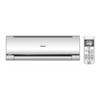
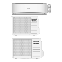
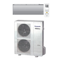
Indoor Unit Outdoor Unit
CS-PS9NKV
CS-PS12NKV
CS-PS18NKV
CS-PS24NKV
CU-PS9NKV
CU-PS12NKV
CU-PS18NKV
CU-PS24NKV
WARNING
This service information is designed for experienced repair technicians only and is not designed for use by the general public.
It does not contain warnings or cautions to advise non-technical individuals of potential dangers in attempting to service a product.
Products powered by electricity should be serviced or repaired only by experienced professional technicians. Any attempt to
service or repair the products dealt with in this service information by anyone else could result in serious injury or death.
PRECAUTION OF LOW TEMPERATURE
In order to avoid frostbit, be assured of no refrigerant leakage during the installation or repairing of refrigerant circuit.

Table of Contents

Questions and Answers:

Panasonic CS-PS9NKV Specifications

General IconGeneral
BrandPanasonic
ModelCS-PS9NKV
CategoryAir Conditioner
LanguageEnglish

Summary

Safety Precautions

Specifications

Location of Controls and Components

Indoor Unit Controls

Identifies controls and indicators on the indoor unit.

Outdoor Unit Components

Identifies components of the outdoor unit.

Remote Control Layout

Details the layout and functions of the remote control.

Dimensions

Indoor Unit Dimensions

Provides dimensional drawings for indoor units CS-PS9/12NKV and CS-PS18/24NKV.

Outdoor Unit Dimensions

Provides dimensional drawings for outdoor units CU-PS9NKV, CU-PS12NKV, CU-PS18NKV, CU-PS24NKV.

Refrigeration Cycle Diagrams

Refrigeration Cycle CS-PS9/12NKV

Diagram illustrating the refrigeration cycle for CS-PS9NKV and CS-PS12NKV models.

Refrigeration Cycle CS-PS18/24NKV

Diagram illustrating the refrigeration cycle for CS-PS18NKV and CS-PS24NKV models.

Block Diagrams

Block Diagram CS-PS9NKV/CU-PS9NKV

Electrical block diagram for CS-PS9NKV/CU-PS9NKV units.

Block Diagram CS-PS12NKV/CU-PS12NKV

Electrical block diagram for CS-PS12NKV/CU-PS12NKV units.

Block Diagram CS-PS18NKV/CU-PS18NKV

Electrical block diagram for CS-PS18NKV/CU-PS18NKV units.

Block Diagram CS-PS24NKV/CU-PS24NKV

Electrical block diagram for CS-PS24NKV/CU-PS24NKV units.

Wiring Connection Diagrams

Indoor Unit Wiring Diagrams

Wiring diagrams for indoor units CS-PS9/12NKV and CS-PS18/24NKV.

Outdoor Unit Wiring Diagrams

Wiring diagrams for outdoor units CU-PS9NKV, CU-PS12NKV, CU-PS18NKV, CU-PS24NKV.

Electronic Circuit Diagrams

Indoor Unit Circuit Diagrams

Electronic circuit diagrams for indoor units CS-PS9/12NKV and CS-PS18/24NKV.

Outdoor Unit Circuit Diagrams

Electronic circuit diagrams for outdoor units CU-PS9NKV, CU-PS12NKV, CU-PS18NKV, CU-PS24NKV.

Printed Circuit Board Layouts

Indoor Unit PCBs

Layouts of main and indicator PCBs for indoor units.

Outdoor Unit PCBs

Layouts of main and noise filter PCBs for outdoor units.

Installation Instructions

Location Selection

Guidelines for selecting optimal installation locations for indoor and outdoor units.

Indoor Unit Installation Procedures

Procedures for installing the indoor unit, including mounting, drilling, piping, and wiring.

Outdoor Unit Installation Procedures

Procedures for outdoor unit installation, piping, evacuation, and connections.

Operation Control

Basic Function and Modes

Explanation of basic operation, internal temperature settings, cooling, and soft dry modes.

Fan Motor Operation

Details on indoor and outdoor fan motor operation, including manual and auto speeds.

Unit Controls and Indicators

Airflow direction, timer control, auto restart, and indicator panel functions.

Protection Control

Various Protection Control Functions

Details on restart, current, IPM, pressure, frequency, and temperature-related protection controls.

Servicing Mode

Auto Off/On Button Operation

Procedures for activating auto operation, test run, and remote control settings via the button.

Remote Control Functions

Explanation of SET, RESET, and Timer buttons on the remote control.

Troubleshooting Guide

Refrigeration Cycle Diagnosis

Guide to diagnosing issues related to the refrigeration cycle using pressure and temperature.

Breakdown Self Diagnosis

Procedures for using the self-diagnosis function to identify and display error codes.

Error Code Table

A comprehensive table of error codes, their meanings, and primary locations to verify.

Troubleshooting Flowcharts

Step-by-step flowcharts for diagnosing specific error codes and malfunctions.

Disassembly and Assembly Instructions

CS-PS9/12NKV Indoor Unit Disassembly

Procedures for disassembling indoor unit components for CS-PS9/12NKV models.

CS-PS18/24NKV Indoor Unit Disassembly

Procedures for disassembling indoor unit components for CS-PS18/24NKV models.

Technical Data

Operation Characteristics

Performance data for cooling, current, pressure, and capacity based on outdoor temperature and piping length.

Exploded View and Replacement Parts List

Indoor Unit Parts

Exploded views and part lists for indoor units CS-PS9/12NKV and CS-PS18/24NKV.

Outdoor Unit Parts

Exploded views and part lists for outdoor units CU-PS9NKV, CU-PS12NKV, CU-PS18NKV, CU-PS24NKV.

Related product manuals