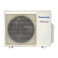
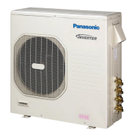
Do you have a question about the Panasonic CU-3E19RBU-5 and is the answer not in the manual?
Details specifications for the CU-3E19RBU-5 model (Wall Mounted & Cassette and Ducted).
Provides specifications for the CU-3E19RBU-5 (Ducted) model, including operational data.
Lists specifications for the CU-4E24RBU-5 (Wall Mounted & Cassette) model, covering performance metrics.
Outlines specifications for the CU-4E24RBU-5 (Ducted) model, detailing electrical and physical data.
Presents physical dimensions and necessary installation space for the CU-3E19RBU-5 outdoor unit.
Shows physical dimensions and installation space requirements for the CU-4E24RBU-5 outdoor unit.
Illustrates the refrigeration cycle for the CU-3E19RBU-5 model, showing component flow.
Depicts the refrigeration cycle for the CU-4E24RBU-5 model, detailing refrigerant flow paths.
Shows the functional block diagram for the CU-3E19RBU-5 outdoor unit, illustrating system components.
Presents the block diagram for the CU-4E24RBU-5 outdoor unit, indicating electrical connections.
Illustrates the wiring connections for the CU-3E19RBU-5 outdoor unit, detailing component wiring.
Provides the wiring diagram for the CU-4E24RBU-5 outdoor unit, showing electrical connections.
Shows the electronic circuit schematic for the CU-3E19RBU-5 model, detailing internal circuitry.
Presents the electronic circuit diagram for the CU-4E24RBU-5 model, illustrating its electronic components.
Shows the layout and component identification for the main printed circuit board.
Illustrates the noise filter printed circuit board layout and connector locations.
Details the display printed circuit board layout, including switches and LEDs.
Provides essential information and check points for installing the CU-3E19RBU-5 model.
Lists key information and check points required for installing the CU-4E24RBU-5 model.
Provides detailed instructions for installing the CU-3E19RBU-5 outdoor unit, including piping and wiring.
Gives detailed instructions for installing the CU-4E24RBU-5 outdoor unit, covering piping and electrical connections.
Explains the controls and logic for cooling operation based on ambient and pipe temperatures.
Details the operation controls and logic for heating mode, including room temperature sampling.
Describes the freeze prevention control logic for cooling operation based on indoor heat exchanger temperature.
Explains the dew prevention control logic for cooling operation based on indoor temperatures.
Details protection against electronic parts overheating during cooling overload conditions.
Covers protection against electronic parts overheating during cooling/dry operations.
Explains the control that restricts compressor frequency during cooling overload.
Describes the control that restricts compressor frequency during heating overload.
Details protection to prevent low pressure drops during extremely low outdoor temperatures.
Explains the deice operation that activates when outdoor pipe and air temperatures are low.
Describes the control that prevents compressor restart within three minutes of stopping.
Explains the control that prevents immediate compressor stop for 30 seconds to cycle oil.
Details the control that adjusts compressor frequency based on total running current.
Covers overheating protection for the IPM (Power Transistor) module and related components.
Describes gas leak detection control to prevent compressor damage.
Details a second gas leak detection control to prevent compressor damage.
Explains the control that detects 3-way valve closure to prevent refrigerant cycle damage.
Covers protection against high discharge pressure during compressor operation.
Describes the control for the compressor crankcase heater to melt ice during heating.
Details servicing procedures for the CU-3E19RBU-5, including pump down and test run operations.
Outlines servicing procedures for the CU-4E24RBU-5, covering pump down and test run operations.
Explains how to use self-diagnosis LEDs and remote control to identify problems and their locations.
Provides troubleshooting steps for various error codes, covering sensor, circuit, and operational faults.
Step-by-step guide for disassembling the CU-3E19RBU-5 outdoor unit, including component removal.
Provides instructions for disassembling the CU-4E24RBU-5 outdoor unit, detailing the removal of external and internal parts.
Presents technical data and operation characteristics for the CU-3E19RBU-5 model.
Provides technical data and performance characteristics for the CU-4E24RBU-5 model.
Shows an exploded view and lists replacement parts for the CU-3E19RBU-5 outdoor unit.
Provides an exploded view and replacement parts list for the CU-4E24RBU-5 outdoor unit.
| Brand | Panasonic |
|---|---|
| Model | CU-3E19RBU-5 |
| Category | Air Conditioner |
| Language | English |


 Loading...