—8—
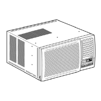
2.2.4 SHROUD
1. Remove the fan. (Refer to section 2.2.3)
2. Remove the 2 screws which fasten the shroud.
3. Remove the shroud. (See Fig. 8)
4. Re-install the component by referring to the
removal procedure, above.
2.3 ELECTRICAL PARTS
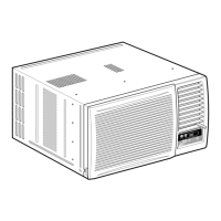
2.3.1 MOTOR
1. Remove the cabinet. (Refer to section 2.1.2)
2. Remove the cover control and disconnect a wire
housing in control box. (Refer to section 2.1.3)
3. Remove the blower. (Refer to section 2.2.2)
4. Remove the fan. (Refer to section 2.2.3)
5. Remove the 4 screws which fasten the motor.
(See Fig. 9)
6. Remove the motor.
7. Re-install the components by referring to the
removal procedure, above.
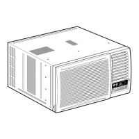
2.3.2 COMPRESSOR
1. Remove the cabinet. (Refer to section 2.1.2)
2. Discharge the refrigerant by using a Refrigerant
Recovery System.
3. Disconnect the 3 leads from the compressor.
4. After purging the unit completely, unbraze the
suction and discharge tubes at the compressor
connections.
5. Remove the 3 nuts and the 3 washers which
fasten the compressor. (See Fig. 10)
6. Remove the compressor.
7. Re-instill the components by referring to the
removal procedure, above.
2.3.3 CAPACITOR
1. Remove the control box. (Refer to section 2.1.3)
2. Remove the screw which fasten the display panel.
3. Remove the screw which located in the front.
4. Open the bottom side of control box.
5. Remove the screw and the clamp which fastens
the capacitor. (See Fig. 11)
6. Disconnect all the leads of capacitor terminals.
7. Re-install the components by referring to the
removal procedure, above. (See Fig. 11)
Figure 8
Figure 9
Figure 10
Figure 11
 Loading...