E
N
G
L
I
S
H
3
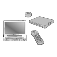
CY-VMR5800N
8
Use this Product Safely (continued)
Aspect button (ASPECT)
Used to select and determine the
ASPECT. (➡ page 11)
Power button (POWER)
Used to turn the power ON and OFF.
(➡ page 10)
Bright button (BRIGHT)
Used to adjust the screen brightness.
(➡ page 12)
Picture button (PICTURE)
Used to adjust the display image.
(➡ page 13)
Power button (NAVI)
Used to turn the power ON and
OFF. (➡ page 10)
Volume control/select buttons
(#, ")
Used to adjust the volume level
of the built-in speaker.
Used to move the cursor.
(➡ pages 10, 12, 13)
Screw holes are provided for attaching the height adjuster fitting
(on the bottom side).
(
1
/
4
-20 UNC screw, maximum length of 4.5 mm)
Standby/power on indicator
[STAND BY (R)/ON (G)]
When the power is off: red
When the power is on: green
Power supply connector
(on the left side)
Remote control sensor
Point the remote control of the
car navigation system
(CN-DV1800EN, CN-DV2000EN,
etc.) at this sensor to operate it.
Enter button (ENTER)
Used to determine the
various settings.
(➡ page 13)
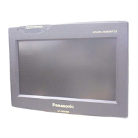
Name of Controls
E
N
G
L
I
S
H
4
CY-VMR5800N
9
WARNING:
≥ In some areas, dashboard installation is prohibited. Observe local regulations when installing the
monitor.
≥ Where and how this unit is installed differs according to the car model concerned. As such, the informa-
tion contained in this installation guide is designed for professional installers and is not intended for non-
technical individuals.
❐ Installation Example (➡ page 17)
Built-in speaker
(on the back)
 Loading...